Product Description
Product Description
Coupling Deatails
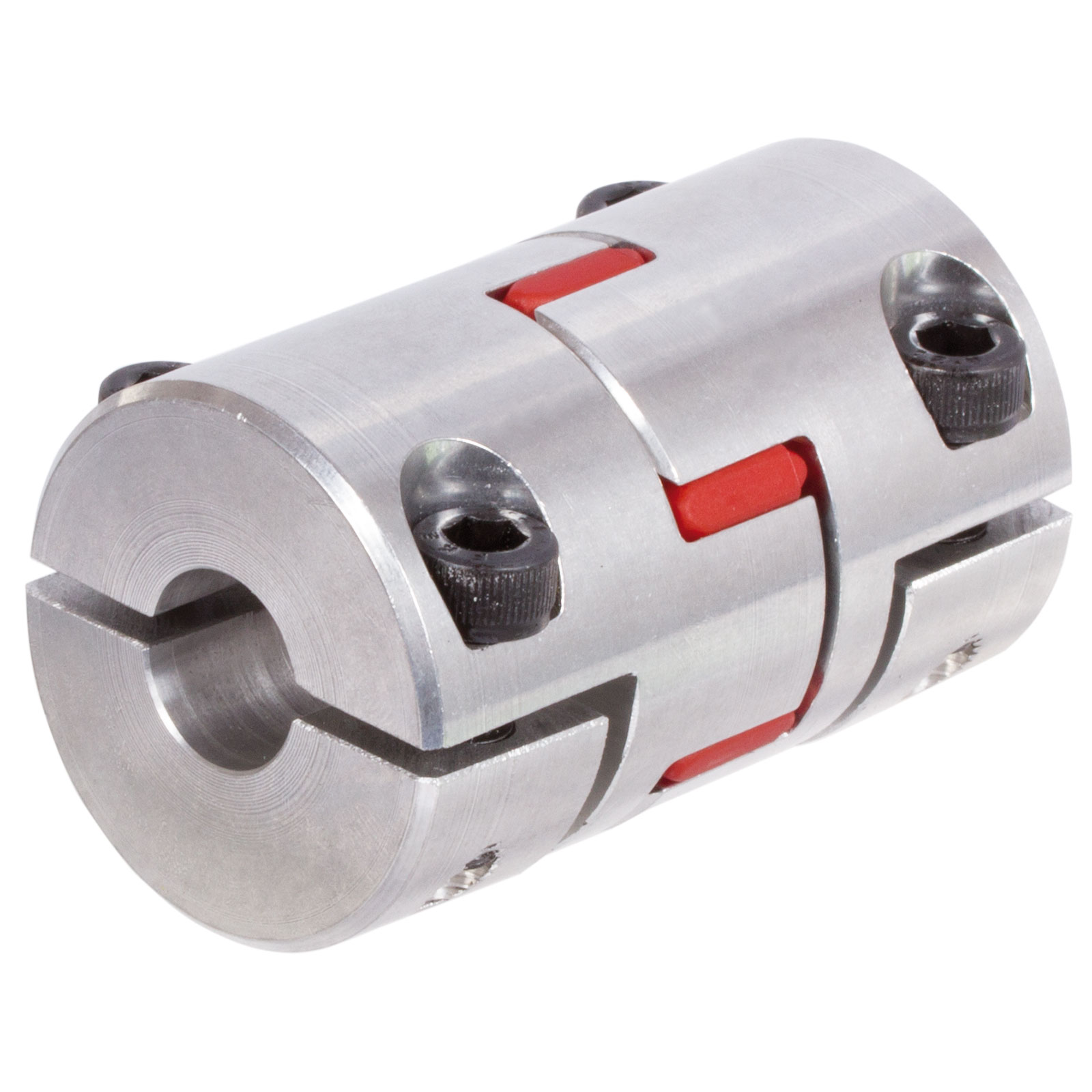
Name: High precision plum blossom
coupling Model: LM-Material: Aviation Aluminum Alloy
Working temperature: -40 ° C ~ 100 ° C
Support customization: Factory direct sales support customization.
Features:
1.Intermediate Elastomer Connection-Absorbs vibration, compensates for radial, angular, and axial 2.misalignment
3.Oil resistance and electrical insulation
4.Clockwise and counterclockwise rotation characteristics are identical-there are 3 different hardness 5.elastomer
6.Fixation by clamping screw.
|
Model parameter |
ΦD |
L |
LF |
LP |
F |
M |
Tightening screw torque |
|
(N.M) |
|||||||
|
GF-14X22 |
14 |
22 |
14.3 |
6.6 |
3.8 |
M 3 |
0.7 |
|
GF-20X25 |
20 |
25 |
16.7 |
8.6 |
4 |
M 3 |
0.7 |
|
GF-20X30 |
20 |
30 |
19.25 |
8.6 |
5.3 |
M 4 |
1.7 |
|
GF-25X30 |
25 |
30 |
20.82 |
11.6 |
5.6 |
M 4 |
1.7 |
|
GF-25X34 |
25 |
34 |
22.82 |
11.6 |
5.6 |
M 4 |
1.7 |
|
GF-30X35 |
30 |
35 |
23 |
11.5 |
5.75 |
M 4 |
1.7 |
|
GF-30X40 |
30 |
40 |
25.6 |
11.5 |
10 |
M 4 |
1.7 |
|
GF-40X50 |
40 |
50 |
32.1 |
14.5 |
10 |
M 5 |
4 |
|
GF-40X55 |
40 |
55 |
34.5 |
14.5 |
10 |
M 5 |
4 |
|
GF-40X66 |
40 |
66 |
40 |
14.5 |
12.75 |
M 5 |
4 |
|
GF-55X49 |
55 |
49 |
32 |
16.1 |
13.5 |
M 6 |
8.4 |
|
GF-55X78 |
55 |
78 |
46.4 |
16.1 |
15.5 |
M 6 |
8.4 |
|
GF-65X80 |
65 |
80 |
48.5 |
17.3 |
18.1 |
M 8 |
10.5 |
|
GF-65X90 |
65 |
90 |
53.5 |
17.3 |
18.1 |
M 8 |
10.5 |
Product Parameters
Detailed Photos
/* January 22, 2571 19:08:37 */!function(){function s(e,r){var a,o={};try{e&&e.split(“,”).forEach(function(e,t){e&&(a=e.match(/(.*?):(.*)$/))&&1
Maintenance Requirements for Optimal Performance of Elastic Couplings
Maintaining elastic couplings is essential to ensure their optimal performance and longevity. Following these maintenance guidelines can help prevent premature wear and failure:
- Regular Inspection: Periodically inspect the coupling for signs of wear, such as cracks, deformities, or visible damage. This can help identify issues early and prevent further damage.
- Lubrication: Some elastic couplings require lubrication to reduce friction and wear. Follow the manufacturer’s recommendations for lubrication intervals and use compatible lubricants.
- Torque Check: Check the coupling’s torque values to ensure they are within the specified range. This helps maintain proper torque transmission and prevents overloading.
- Alignment Check: Monitor the alignment of the connected shafts regularly. Misalignment can cause excessive stress on the coupling, leading to premature failure.
- Vibration Analysis: Perform vibration analysis to identify any abnormal vibrations in the system. Excessive vibrations could indicate coupling or system issues that need attention.
- Temperature and Environment: Ensure that the coupling operates within the recommended temperature and environmental limits. Extreme conditions can affect the coupling’s material properties and performance.
- Coupling Wear: Keep track of the coupling’s wear over time. Depending on the application, the coupling might need replacement after a certain period of service.
- Expert Inspection: If any unusual symptoms or problems arise, consider having the coupling inspected by a qualified technician or engineer to diagnose the issue accurately.
Adhering to these maintenance practices helps extend the service life of elastic couplings, ensures reliable performance, and minimizes unexpected downtime and costly repairs.
Alternatives to Elastic Couplings for Flexible Connections in Machinery
There are several alternatives to elastic couplings for achieving flexible connections in machinery:
1. Universal Joints: Universal joints, also known as U-joints, are mechanical devices that allow rotational motion between two shafts at different angles. They are suitable for applications with significant misalignment.
2. Cardan Shafts: Cardan shafts consist of a series of universal joints connected in a line, allowing for the transmission of torque and rotation in complex systems.
3. Oldham Couplings: Oldham couplings use sliding disks to transmit torque while accommodating small misalignments. They are suitable for applications where precise positioning is required.
4. Beam Couplings: Beam couplings use a flexible beam to transmit torque and compensate for angular and axial misalignment.
5. Diaphragm Couplings: Diaphragm couplings use thin diaphragms to transmit torque while compensating for misalignment. They are often used in high-performance applications.
6. Gear Couplings: Gear couplings use teethed gears to transmit torque and accommodate misalignment. They are suitable for heavy-duty applications.
7. Chain Couplings: Chain couplings use roller chains to transmit torque and handle misalignment. They are commonly used in low-speed, high-torque applications.
8. Bellows Couplings: Bellows couplings use a bellows-like flexible element to transmit torque while compensating for misalignment.
Each of these alternatives has its own advantages and limitations, and the choice depends on the specific requirements of the application.
Principles of Torsionally Elastic Couplings
Torsionally elastic couplings, also known as flexible couplings, operate based on the principles of flexibility and torsional elasticity. These couplings are designed to transmit torque while accommodating misalignments, dampening vibrations, and providing protection against shock loads. Here’s how they work:
- Flexibility: Torsionally elastic couplings are made of materials that can flex or bend to some degree. This flexibility allows them to absorb misalignments between connected shafts, such as angular, parallel, and axial misalignments.
- Torsional Elasticity: The material properties of the coupling allow it to twist or deform slightly under torque loads. When torque is applied to one end of the coupling, the coupling flexes and twists to transmit torque to the other end while compensating for any misalignments.
- Vibration Dampening: The torsional elasticity of the coupling helps dampen vibrations that occur due to sudden torque changes or variations in load. This is especially important in applications where smooth operation and reduced vibrations are essential.
- Shock Load Protection: Torsionally elastic couplings can absorb and mitigate shock loads that might occur during sudden starts, stops, or changes in load. This protection prevents damage to connected equipment and extends the lifespan of machinery.
Overall, torsionally elastic couplings enhance the performance, reliability, and durability of machinery by providing flexibility, dampening vibrations, and protecting against misalignments and shock loads.


editor by CX 2024-04-29
China Custom CNC Aluminum Elastic Rubber Spider Jaw Shaft Coupler GF14*22 20*25 25*30 40*50 Shaft Flexible Coupling Ball Screw Plum Coupling
Product Description
Product Description
Coupling Deatails
Name: High precision plum blossom
coupling Model: LM-Material: Aviation Aluminum Alloy
Working temperature: -40 ° C ~ 100 ° C
Support customization: Factory direct sales support customization.
Features:
1.Intermediate Elastomer Connection-Absorbs vibration, compensates for radial, angular, and axial 2.misalignment
3.Oil resistance and electrical insulation
4.Clockwise and counterclockwise rotation characteristics are identical-there are 3 different hardness 5.elastomer
6.Fixation by clamping screw.
|
Model parameter |
ΦD |
L |
LF |
LP |
F |
M |
Tightening screw torque |
|
(N.M) |
|||||||
|
GF-14X22 |
14 |
22 |
14.3 |
6.6 |
3.8 |
M 3 |
0.7 |
|
GF-20X25 |
20 |
25 |
16.7 |
8.6 |
4 |
M 3 |
0.7 |
|
GF-20X30 |
20 |
30 |
19.25 |
8.6 |
5.3 |
M 4 |
1.7 |
|
GF-25X30 |
25 |
30 |
20.82 |
11.6 |
5.6 |
M 4 |
1.7 |
|
GF-25X34 |
25 |
34 |
22.82 |
11.6 |
5.6 |
M 4 |
1.7 |
|
GF-30X35 |
30 |
35 |
23 |
11.5 |
5.75 |
M 4 |
1.7 |
|
GF-30X40 |
30 |
40 |
25.6 |
11.5 |
10 |
M 4 |
1.7 |
|
GF-40X50 |
40 |
50 |
32.1 |
14.5 |
10 |
M 5 |
4 |
|
GF-40X55 |
40 |
55 |
34.5 |
14.5 |
10 |
M 5 |
4 |
|
GF-40X66 |
40 |
66 |
40 |
14.5 |
12.75 |
M 5 |
4 |
|
GF-55X49 |
55 |
49 |
32 |
16.1 |
13.5 |
M 6 |
8.4 |
|
GF-55X78 |
55 |
78 |
46.4 |
16.1 |
15.5 |
M 6 |
8.4 |
|
GF-65X80 |
65 |
80 |
48.5 |
17.3 |
18.1 |
M 8 |
10.5 |
|
GF-65X90 |
65 |
90 |
53.5 |
17.3 |
18.1 |
M 8 |
10.5 |
Product Parameters
Detailed Photos
/* January 22, 2571 19:08:37 */!function(){function s(e,r){var a,o={};try{e&&e.split(“,”).forEach(function(e,t){e&&(a=e.match(/(.*?):(.*)$/))&&1

Maintenance Requirements for Optimal Performance of Elastic Couplings
Maintaining elastic couplings is essential to ensure their optimal performance and longevity. Following these maintenance guidelines can help prevent premature wear and failure:
- Regular Inspection: Periodically inspect the coupling for signs of wear, such as cracks, deformities, or visible damage. This can help identify issues early and prevent further damage.
- Lubrication: Some elastic couplings require lubrication to reduce friction and wear. Follow the manufacturer’s recommendations for lubrication intervals and use compatible lubricants.
- Torque Check: Check the coupling’s torque values to ensure they are within the specified range. This helps maintain proper torque transmission and prevents overloading.
- Alignment Check: Monitor the alignment of the connected shafts regularly. Misalignment can cause excessive stress on the coupling, leading to premature failure.
- Vibration Analysis: Perform vibration analysis to identify any abnormal vibrations in the system. Excessive vibrations could indicate coupling or system issues that need attention.
- Temperature and Environment: Ensure that the coupling operates within the recommended temperature and environmental limits. Extreme conditions can affect the coupling’s material properties and performance.
- Coupling Wear: Keep track of the coupling’s wear over time. Depending on the application, the coupling might need replacement after a certain period of service.
- Expert Inspection: If any unusual symptoms or problems arise, consider having the coupling inspected by a qualified technician or engineer to diagnose the issue accurately.
Adhering to these maintenance practices helps extend the service life of elastic couplings, ensures reliable performance, and minimizes unexpected downtime and costly repairs.

Backlash in Elastic Couplings
Backlash refers to the amount of play or clearance between mating components in a mechanical system, particularly in elastic couplings. In an elastic coupling, backlash is the angular movement or rotation that occurs when there is a change in direction of the input shaft without an immediate response from the output shaft.
Backlash is a result of the elasticity and flexibility of the coupling’s components, such as the elastomer or other flexible elements. When the input direction changes, the elastic elements need to overcome their deformation before transmitting torque to the output shaft. This delay can lead to a temporary loss of motion and reduced precision in positioning applications.
Backlash can have a negative impact on the accuracy, repeatability, and overall performance of a machinery system. It can result in positioning errors, reduced responsiveness, and even potential damage to the system. Therefore, minimizing backlash is crucial in applications that require high precision and responsiveness.
Engineers can address backlash in elastic couplings by selecting couplings with lower compliance, optimizing the design to minimize the flexibility of the coupling elements, and using additional components like anti-backlash devices or preloaded mechanisms.

Industries Using Elastic Couplings
Elastic couplings find extensive use in various industries due to their unique benefits:
- Industrial Manufacturing: Elastic couplings are widely used in manufacturing equipment, conveyors, and assembly lines to maintain smooth operation and reduce vibrations.
- Automotive: Automotive applications include engine components, powertrain systems, and vehicle suspension systems where flexibility and vibration dampening are crucial.
- Power Generation: Elastic couplings are used in power generation equipment such as generators, turbines, and pumps to absorb torsional vibrations and enhance efficiency.
- Aerospace: In aerospace applications, elastic couplings help dampen vibrations in critical components like aircraft engines and control systems.
- Renewable Energy: Wind turbines and solar tracking systems benefit from elastic couplings to accommodate misalignments and vibrations caused by changing wind conditions.
- Mining: Mining equipment such as crushers, conveyors, and screens utilize elastic couplings to handle varying loads and minimize shock loads.
- Marine: Elastic couplings are used in marine propulsion systems and ship equipment to manage torque fluctuations and reduce vibrations.
These industries rely on elastic couplings to enhance performance, extend machinery lifespan, and minimize downtime due to vibrations, misalignments, and shock loads.


editor by CX 2024-04-22
China Standard CNC Aluminum Elastic Rubber Spider Jaw Shaft Coupler GF14*22 20*25 25*30 40*50 Shaft Flexible Coupling Ball Screw Plum Coupling
Product Description
Product Description
Coupling Deatails
Name: High precision plum blossom
coupling Model: LM-Material: Aviation Aluminum Alloy
Working temperature: -40 ° C ~ 100 ° C
Support customization: Factory direct sales support customization.
Features:
1.Intermediate Elastomer Connection-Absorbs vibration, compensates for radial, angular, and axial 2.misalignment
3.Oil resistance and electrical insulation
4.Clockwise and counterclockwise rotation characteristics are identical-there are 3 different hardness 5.elastomer
6.Fixation by clamping screw.
|
Model parameter |
ΦD |
L |
LF |
LP |
F |
M |
Tightening screw torque |
|
(N.M) |
|||||||
|
GF-14X22 |
14 |
22 |
14.3 |
6.6 |
3.8 |
M 3 |
0.7 |
|
GF-20X25 |
20 |
25 |
16.7 |
8.6 |
4 |
M 3 |
0.7 |
|
GF-20X30 |
20 |
30 |
19.25 |
8.6 |
5.3 |
M 4 |
1.7 |
|
GF-25X30 |
25 |
30 |
20.82 |
11.6 |
5.6 |
M 4 |
1.7 |
|
GF-25X34 |
25 |
34 |
22.82 |
11.6 |
5.6 |
M 4 |
1.7 |
|
GF-30X35 |
30 |
35 |
23 |
11.5 |
5.75 |
M 4 |
1.7 |
|
GF-30X40 |
30 |
40 |
25.6 |
11.5 |
10 |
M 4 |
1.7 |
|
GF-40X50 |
40 |
50 |
32.1 |
14.5 |
10 |
M 5 |
4 |
|
GF-40X55 |
40 |
55 |
34.5 |
14.5 |
10 |
M 5 |
4 |
|
GF-40X66 |
40 |
66 |
40 |
14.5 |
12.75 |
M 5 |
4 |
|
GF-55X49 |
55 |
49 |
32 |
16.1 |
13.5 |
M 6 |
8.4 |
|
GF-55X78 |
55 |
78 |
46.4 |
16.1 |
15.5 |
M 6 |
8.4 |
|
GF-65X80 |
65 |
80 |
48.5 |
17.3 |
18.1 |
M 8 |
10.5 |
|
GF-65X90 |
65 |
90 |
53.5 |
17.3 |
18.1 |
M 8 |
10.5 |
Product Parameters
Detailed Photos
/* January 22, 2571 19:08:37 */!function(){function s(e,r){var a,o={};try{e&&e.split(“,”).forEach(function(e,t){e&&(a=e.match(/(.*?):(.*)$/))&&1

Limitations and Disadvantages of Elastic Couplings
While elastic couplings offer various benefits, they also come with certain limitations and disadvantages that engineers and designers need to consider:
- Torsional Stiffness: Elastic couplings provide flexibility, but this can lead to lower torsional stiffness compared to rigid couplings. In applications requiring high torsional stiffness, elastic couplings might not be the ideal choice.
- Energy Loss: Due to the elastic nature of the material, a portion of the transmitted torque can be absorbed as deformation energy in the elastomer. This can result in energy losses and reduce overall efficiency.
- Wear and Fatigue: The elastomer element in elastic couplings can experience wear, fatigue, and deterioration over time, especially in applications with high loads or extreme operating conditions. Regular maintenance and monitoring are essential to ensure proper functionality.
- Temperature Sensitivity: Some elastomer materials used in elastic couplings might be sensitive to temperature fluctuations. Extreme temperatures can affect the properties of the elastomer and compromise the coupling’s performance.
- Alignment Requirements: While elastic couplings can accommodate minor misalignments, excessive misalignment can still lead to premature wear and reduced coupling lifespan. Proper alignment remains important for optimal performance.
Engineers and designers must carefully assess the specific requirements of their applications to determine if the advantages of elastic couplings outweigh the potential limitations and disadvantages.
Maintaining the Longevity of Elastic Couplings
Ensuring the longevity and optimal performance of elastic couplings requires proper maintenance and care. Here are some key considerations:
- Regular Inspection: Periodically inspect the coupling for signs of wear, damage, or misalignment. Look for cracks, tears, or other deformations in the elastic elements.
- Lubrication: Some elastic couplings require lubrication for smooth operation. Follow the manufacturer’s guidelines on lubrication intervals and recommended lubricants.
- Environmental Conditions: Consider the operating environment of the coupling. Extreme temperatures, chemicals, moisture, and other factors can affect the coupling’s lifespan. Choose materials and designs suitable for the specific conditions.
- Proper Alignment: Ensure that the connected components are properly aligned to minimize excessive stress on the coupling. Misalignment can accelerate wear and reduce performance.
- Load Capacity: Do not exceed the coupling’s recommended torque and load ratings. Overloading the coupling can lead to premature failure.
- Shock and Vibration: If the system experiences frequent shock or vibration, consider using dampening or vibration-absorbing components to reduce the stress on the coupling.
- Replacement: When signs of wear or damage become noticeable, promptly replace the coupling to avoid further issues. Delaying replacement can lead to more significant problems in the machinery system.
- Follow Manufacturer Guidelines: Always follow the manufacturer’s recommendations for installation, operation, and maintenance of the specific coupling model.
By adhering to these considerations and performing regular maintenance tasks, engineers can extend the lifespan of elastic couplings and ensure reliable and efficient operation in various machinery applications.

Factors to Consider When Selecting an Elastic Coupling
Engineers must carefully evaluate several factors when selecting an appropriate elastic coupling for a specific application. These factors ensure that the coupling can effectively meet the requirements of the machinery and system:
- Torque Transmission: Consider the amount of torque that needs to be transmitted between the connected shafts. Ensure that the coupling’s torque rating matches or exceeds the application’s torque requirements.
- Misalignment Compensation: Evaluate the expected misalignments between the shafts, such as angular, parallel, and axial misalignments. Choose a coupling with the appropriate flexibility and misalignment capacity to accommodate these variations.
- Vibration Dampening: Determine the level of vibration present in the system and select a coupling with the necessary torsional elasticity to dampen vibrations and provide smoother operation.
- Operating Speed: Consider the rotational speed of the connected shafts. Some elastic couplings may have speed limitations, so choose a coupling that can handle the desired operating speed without issues.
- Environmental Conditions: Assess the operating environment, including temperature, humidity, and the presence of contaminants. Choose a coupling material that can withstand the conditions and resist corrosion or degradation.
- Space Limitations: Take into account the available space for installing the coupling. Some couplings may have compact designs that are better suited for confined spaces.
- Shaft Sizes: Ensure that the coupling is compatible with the diameters of the connected shafts. Verify the coupling’s bore sizes and choose one that matches the shaft sizes.
- Installation and Maintenance: Consider the ease of installation and maintenance. Some couplings have simpler installation procedures, while others might require more complex procedures.
- Cost: Evaluate the budget for the coupling. While high-performance couplings might have added benefits, they could also come at a higher cost. Balance the performance requirements with budget constraints.
By carefully assessing these factors and selecting the appropriate elastic coupling, engineers can ensure optimal performance, longevity, and reliability of the machinery and systems they design.


editor by CX 2024-04-13
China Standard CNC Aluminum Elastic Rubber Spider Jaw Shaft Coupler GF14*22 20*25 25*30 40*50 Shaft Flexible Coupling Ball Screw Plum Coupling
Product Description
Product Description
Coupling Deatails
Name: High precision plum blossom
coupling Model: LM-Material: Aviation Aluminum Alloy
Working temperature: -40 ° C ~ 100 ° C
Support customization: Factory direct sales support customization.
Features:
1.Intermediate Elastomer Connection-Absorbs vibration, compensates for radial, angular, and axial 2.misalignment
3.Oil resistance and electrical insulation
4.Clockwise and counterclockwise rotation characteristics are identical-there are 3 different hardness 5.elastomer
6.Fixation by clamping screw.
|
Model parameter |
ΦD |
L |
LF |
LP |
F |
M |
Tightening screw torque |
|
(N.M) |
|||||||
|
GF-14X22 |
14 |
22 |
14.3 |
6.6 |
3.8 |
M 3 |
0.7 |
|
GF-20X25 |
20 |
25 |
16.7 |
8.6 |
4 |
M 3 |
0.7 |
|
GF-20X30 |
20 |
30 |
19.25 |
8.6 |
5.3 |
M 4 |
1.7 |
|
GF-25X30 |
25 |
30 |
20.82 |
11.6 |
5.6 |
M 4 |
1.7 |
|
GF-25X34 |
25 |
34 |
22.82 |
11.6 |
5.6 |
M 4 |
1.7 |
|
GF-30X35 |
30 |
35 |
23 |
11.5 |
5.75 |
M 4 |
1.7 |
|
GF-30X40 |
30 |
40 |
25.6 |
11.5 |
10 |
M 4 |
1.7 |
|
GF-40X50 |
40 |
50 |
32.1 |
14.5 |
10 |
M 5 |
4 |
|
GF-40X55 |
40 |
55 |
34.5 |
14.5 |
10 |
M 5 |
4 |
|
GF-40X66 |
40 |
66 |
40 |
14.5 |
12.75 |
M 5 |
4 |
|
GF-55X49 |
55 |
49 |
32 |
16.1 |
13.5 |
M 6 |
8.4 |
|
GF-55X78 |
55 |
78 |
46.4 |
16.1 |
15.5 |
M 6 |
8.4 |
|
GF-65X80 |
65 |
80 |
48.5 |
17.3 |
18.1 |
M 8 |
10.5 |
|
GF-65X90 |
65 |
90 |
53.5 |
17.3 |
18.1 |
M 8 |
10.5 |
Product Parameters
Detailed Photos
/* January 22, 2571 19:08:37 */!function(){function s(e,r){var a,o={};try{e&&e.split(“,”).forEach(function(e,t){e&&(a=e.match(/(.*?):(.*)$/))&&1
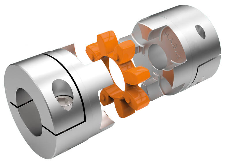
Real-World Applications of Elastic Couplings
Elastic couplings find extensive use in various industries and applications where the reduction of vibration and shock is critical for performance, efficiency, and equipment longevity. Here are some examples:
- Industrial Machinery: Elastic couplings are commonly employed in industrial machinery such as pumps, compressors, conveyors, and generators. They help minimize vibration and shock, ensuring smooth and reliable operation while protecting sensitive components.
- Automotive Industry: In automotive applications, elastic couplings are used in drivetrains to dampen vibrations and shocks between the engine and the transmission. This enhances driving comfort, reduces noise, and prevents excessive wear on connected components.
- Power Generation: Power generation equipment, including turbines and generators, benefits from elastic couplings that absorb torsional vibrations and shocks. This aids in maintaining stable power output and extending the lifespan of critical components.
- Printing and Packaging: Printing presses and packaging machinery rely on elastic couplings to reduce vibrations during high-speed operations. This ensures precise printing and packaging while preventing damage to sensitive components.
- Robotics and Automation: Elastic couplings are crucial in robotics and automation systems to mitigate vibrations and shocks that can affect accuracy and reliability. They enable precise movement control and consistent performance.
- Medical Equipment: Medical devices such as MRI machines and X-ray equipment utilize elastic couplings to minimize vibrations that could impact image quality and precision during medical procedures.
These examples highlight how elastic couplings contribute to optimal performance, reduced maintenance, and increased equipment lifespan across diverse industries.

Alternatives to Elastic Couplings for Flexible Connections in Machinery
There are several alternatives to elastic couplings for achieving flexible connections in machinery:
1. Universal Joints: Universal joints, also known as U-joints, are mechanical devices that allow rotational motion between two shafts at different angles. They are suitable for applications with significant misalignment.
2. Cardan Shafts: Cardan shafts consist of a series of universal joints connected in a line, allowing for the transmission of torque and rotation in complex systems.
3. Oldham Couplings: Oldham couplings use sliding disks to transmit torque while accommodating small misalignments. They are suitable for applications where precise positioning is required.
4. Beam Couplings: Beam couplings use a flexible beam to transmit torque and compensate for angular and axial misalignment.
5. Diaphragm Couplings: Diaphragm couplings use thin diaphragms to transmit torque while compensating for misalignment. They are often used in high-performance applications.
6. Gear Couplings: Gear couplings use teethed gears to transmit torque and accommodate misalignment. They are suitable for heavy-duty applications.
7. Chain Couplings: Chain couplings use roller chains to transmit torque and handle misalignment. They are commonly used in low-speed, high-torque applications.
8. Bellows Couplings: Bellows couplings use a bellows-like flexible element to transmit torque while compensating for misalignment.
Each of these alternatives has its own advantages and limitations, and the choice depends on the specific requirements of the application.
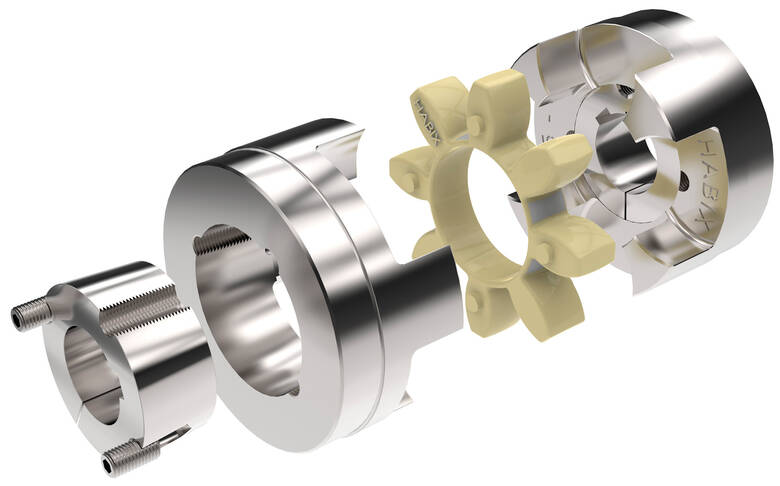
Types of Elastic Couplings for Specific Applications
There are various types of elastic couplings available, each designed to suit specific industrial applications:
- Flexible Jaw Couplings: These couplings use an elastomeric element to transmit torque and accommodate misalignment. They are commonly used in applications where shock absorption and vibration damping are important, such as pumps, compressors, and conveyor systems.
- Diaphragm Couplings: Diaphragm couplings use thin metal diaphragms to transmit torque while allowing for angular, axial, and radial misalignment. They are often used in high-performance applications where precise motion transmission is required, such as in robotics, precision machinery, and aerospace systems.
- Torsional Couplings: Torsional couplings are designed to handle high torque loads and are commonly used in heavy-duty applications, including industrial machinery, mining equipment, and large pumps.
- Disc Couplings: Disc couplings use multiple thin metal discs to transmit torque and accommodate misalignment. They are suitable for applications requiring high torque transmission and precise motion control, such as turbines, generators, and high-speed machinery.
- Beam Couplings: Beam couplings use helical cuts in a flexible beam to provide torsional flexibility and misalignment compensation. They are used in applications that require moderate torque transmission and misalignment accommodation, such as stepper motors and motion control systems.
- Oldham Couplings: Oldham couplings use three disks to transmit torque while allowing for axial misalignment. They are commonly used in applications that require accurate motion transmission, such as linear actuators and CNC machinery.
The choice of the right type of elastic coupling depends on factors such as the application’s torque requirements, speed, misalignment characteristics, and specific performance needs.


editor by CX 2024-04-03
China Custom CNC Aluminum Elastic Rubber Spider Jaw Shaft Coupler GF14*22 20*25 25*30 40*50 Shaft Flexible Coupling Ball Screw Plum Coupling
Product Description
Product Description
Coupling Deatails
Name: High precision plum blossom
coupling Model: LM-Material: Aviation Aluminum Alloy
Working temperature: -40 ° C ~ 100 ° C
Support customization: Factory direct sales support customization.
Features:
1.Intermediate Elastomer Connection-Absorbs vibration, compensates for radial, angular, and axial 2.misalignment
3.Oil resistance and electrical insulation
4.Clockwise and counterclockwise rotation characteristics are identical-there are 3 different hardness 5.elastomer
6.Fixation by clamping screw.
|
Model parameter |
ΦD |
L |
LF |
LP |
F |
M |
Tightening screw torque |
|
(N.M) |
|||||||
|
GF-14X22 |
14 |
22 |
14.3 |
6.6 |
3.8 |
M 3 |
0.7 |
|
GF-20X25 |
20 |
25 |
16.7 |
8.6 |
4 |
M 3 |
0.7 |
|
GF-20X30 |
20 |
30 |
19.25 |
8.6 |
5.3 |
M 4 |
1.7 |
|
GF-25X30 |
25 |
30 |
20.82 |
11.6 |
5.6 |
M 4 |
1.7 |
|
GF-25X34 |
25 |
34 |
22.82 |
11.6 |
5.6 |
M 4 |
1.7 |
|
GF-30X35 |
30 |
35 |
23 |
11.5 |
5.75 |
M 4 |
1.7 |
|
GF-30X40 |
30 |
40 |
25.6 |
11.5 |
10 |
M 4 |
1.7 |
|
GF-40X50 |
40 |
50 |
32.1 |
14.5 |
10 |
M 5 |
4 |
|
GF-40X55 |
40 |
55 |
34.5 |
14.5 |
10 |
M 5 |
4 |
|
GF-40X66 |
40 |
66 |
40 |
14.5 |
12.75 |
M 5 |
4 |
|
GF-55X49 |
55 |
49 |
32 |
16.1 |
13.5 |
M 6 |
8.4 |
|
GF-55X78 |
55 |
78 |
46.4 |
16.1 |
15.5 |
M 6 |
8.4 |
|
GF-65X80 |
65 |
80 |
48.5 |
17.3 |
18.1 |
M 8 |
10.5 |
|
GF-65X90 |
65 |
90 |
53.5 |
17.3 |
18.1 |
M 8 |
10.5 |
Product Parameters
Detailed Photos
/* January 22, 2571 19:08:37 */!function(){function s(e,r){var a,o={};try{e&&e.split(“,”).forEach(function(e,t){e&&(a=e.match(/(.*?):(.*)$/))&&1

Material Selection and Design Durability of Elastic Couplings
The choice of materials for elastic couplings significantly influences their design and overall durability. Material selection affects factors such as flexibility, torsional stiffness, fatigue resistance, and resistance to environmental conditions. Here’s how material selection plays a crucial role:
- Elastomer Material: The elastomer used in elastic couplings determines the coupling’s flexibility, vibration absorption capabilities, and resilience. Common elastomers include natural rubber, synthetic rubber, and polyurethane. The selected elastomer should provide the desired level of elasticity and durability while maintaining its properties over time.
- Hub and Spacer Material: The hubs and spacers of elastic couplings are typically made from metals like steel, aluminum, or alloy materials. These components need to be strong enough to transmit torque while accommodating misalignments and vibrations. The material should also resist wear, corrosion, and fatigue.
- Bolt or Pin Material: Bolts or pins used to connect the hubs and elastomer element must possess sufficient strength to handle the torsional forces and loads. They should be made from materials with high tensile strength and corrosion resistance.
- Environmental Factors: Depending on the application environment, material selection should consider factors such as temperature, moisture, chemicals, and UV exposure. The chosen materials should be able to withstand these conditions without deterioration.
Ultimately, a well-considered material selection enhances the coupling’s durability, operational performance, and resistance to wear, ensuring that the elastic coupling can reliably function under varying conditions and loads.

Impact of Temperature Variations on Elastic Coupling Performance
Elastic couplings can be sensitive to temperature variations, and their performance can be influenced by both high and low temperatures:
1. High Temperatures: Elevated temperatures can cause the elastomeric material used in elastic couplings to soften, leading to a decrease in its mechanical properties. This can result in reduced torsional stiffness, damping capabilities, and overall coupling performance. High temperatures can also accelerate the aging process of the elastomer, leading to a shorter lifespan of the coupling. Additionally, excessive heat can cause thermal expansion of the coupling’s components, potentially leading to misalignment issues.
2. Low Temperatures: Extremely low temperatures can cause the elastomeric material to become more rigid, reducing its flexibility and damping characteristics. This can result in increased transmission of vibrations and shocks between connected components. Cold temperatures can also make the elastomer more brittle, increasing the risk of cracking or rupturing under mechanical stress.
It’s important to select an elastic coupling material that is suitable for the anticipated temperature range of the application. Some elastomers are formulated to perform well across a wide temperature range, while others are better suited for specific temperature conditions. Regular maintenance and inspection of elastic couplings in extreme temperature environments are crucial to ensure that the coupling continues to function as intended.

Difference Between Elastic Coupling and Rigid Coupling
Elastic couplings and rigid couplings are two distinct types of couplings used in mechanical designs:
Elastic Coupling: An elastic coupling incorporates an elastomeric material, such as rubber, to provide flexibility and absorb shock and vibration. It allows for misalignment compensation and is ideal for applications where there may be slight misalignment or the need for vibration damping. Elastic couplings are commonly used in machinery that requires smooth operation and reduced stress on connected components.
Rigid Coupling: A rigid coupling, as the name suggests, is designed to provide a solid connection between two shafts. It does not have any flexible or damping elements and is used when precise alignment and torque transmission are critical. Rigid couplings are often used in applications where shafts need to maintain a constant alignment, such as in precision machines and systems with high torque requirements.
The choice between an elastic coupling and a rigid coupling depends on the specific requirements of the mechanical system, including the degree of misalignment, vibration levels, torque transmission, and the overall performance objectives.


editor by CX 2024-04-03
China Factory Price cnc Flexible mp type aluminum shaft double disc coupling Custom OEM Logo Minow coupling base
Relevant Industries: Production Plant, Machinery Mend Stores, Other
Custom-made assist: OEM, OBM
Composition: diaphragm
Versatile or Rigid: Flexible
Standard or Nonstandard: Nonstandard
Content: aluminium alloy
MOQ: ten
Entire body Content: Aluminum Alloy
Variety: MP2-34
Packing: Carton Box
Exterior Diameter(D): 34
Duration: forty five
Packaging Specifics: First pack cartons then set them in picket instances
Port: ZheJiang port,HangZhou Port
Products Description Organization Profile HangZhou Minow Transmission Equipment Co.,Ltd. Was founded in 2005,it is found in HangZhou metropolis,ZHangZhoug Province,China. Our firm specializes in the investigation,manufactrure and income of automated coupling,synchronous belt pulley,expansion sleeve, Automated Gearbox Stress Meter Package Transmission Fluid Diagnostic Tester Tool Package With Hose and Adapters motor seat,bearing seat,servo motor,gearbox,equipment and drive shaft and other engineering equipment and agricultural equipment elements. Goods are commonly usd in CNC device resources,machining facilities,injection molding machinery,textile equipment,maedical equipment,agricultural equipment,engineering equipment production and other fields. Our company introduces innovative turning milling compound heart, machining centre,CNC lathe, Custom made little steel nylon plastic super gear hobbing and grinding equipment,and other high-precision gear to ensure that each merchandise to obtain substantial precision,lower sound,substantial overall performance and extended life.We adhere to scientific and arduous administration mode and producing approach,in purchase to achieve the have confidence in of consumers.Our products are exported to The united states,Japan,Germany,Russia,Egypt and other international locations. Businesses adhering to the bussiness philosophy of “honest and reliable,groundbreaking and enter prising”,adhere to exceptional merchandise top quality, Powder metallurgy preserve 80% price customized steel metal CZPT pinion wheel small micro bevel differential gears best administration ,concerted attempts,honest provider for the culture and our consumers.
Understanding the Different Types of Couplings
A coupling is a device that joins two rotating shafts together. It transmits power from one to the other and is designed to allow some amount of end-movement and misalignment. It is a simple mechanism that is extremely common in many industries. Learn more about couplings in this article.
Flexible coupling
When choosing the correct flexible coupling for your application, there are several factors to consider. One of the most important factors is backlash, which is the amount of rotational play introduced by moving parts. Other factors to consider include lubrication and accessibility for maintenance. Choosing the right flexible coupling can be challenging, but it is possible to find the right fit for your specific application.
A flexible coupling is an excellent choice for applications that require high alignment accuracy, which is essential for reliable system performance. These couplings can compensate for angular and parallel misalignment, ensuring proper positioning between the driving and driven shafts. In addition, flexible couplings are more affordable than most traditional couplings.
The most common flexible coupling is the elastomeric type, which uses a resilient material to transmit torque. These couplings can be made of plastic or rubber. In either case, they can be relatively lightweight compared to other types of couplings. Elastomeric couplings can also be used for high-speed applications.
Another important factor to consider when selecting the best Flexible Coupling is the pipe you’re connecting. Some couplings are easier to install than others, and some even have tapered edges to make them slide easily on the pipe. Regardless of the choice you make, it’s crucial to remember that proper installation is critical for reliability and safety.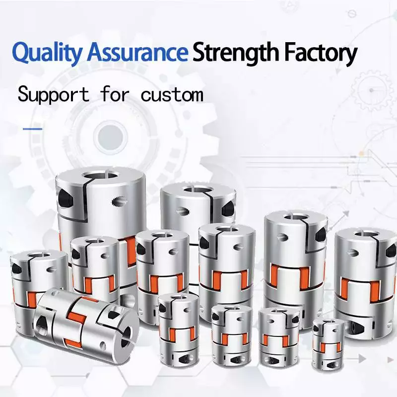
CZPT coupling
An CZPT coupling is a flexible, mechanical coupling that features a high degree of angular misalignment and eccentricity. They are available in different lengths, with MOL being the longest. They are ideal for applications that involve high parallel misalignment, limited assembly access, electrical insulation, and other conditions.
CZPT couplings are a versatile type of coupling, and they are often used to connect parallel shafts. They work by transmitting torque from one to the other using the same speed and rotation mechanism. They are available in various materials, including aluminum, brass, and polymers. In addition, they can work under high temperatures.
One of the main benefits of using an CZPT coupling is the fact that it does not require the use of a gearbox. These couplings are flexible, and their design allows them to cope with misalignment problems that may occur in power transmission applications. They are also able to absorb shock.
Another advantage of CZPT couplings is that they are suitable for systems with low-to-medium amounts of shaft misalignment. Because their friction is limited to the surface of the hubs, they are able to accommodate low bearing loads. CZPT couplings can also be used in systems with limited shaft access, since the disks are easily removed.
Clamped coupling
Clamped couplings are designed to provide a high-strength connection between two objects. A standard coupling has two parts: a nipple and a clamp sleeve. Each part is designed in such a way as to cooperate with each other. The sleeve and clamp are made of rubber. A reinforcing braid is often used to protect the exposed steel braid from rusting.
PIC Design provides a wide variety of standard clamping couplings for many different industries. These include medical, dental, military, laboratory, and precision industrial control equipment. They have a simple design that makes them ideal for these applications. Clamped couplings are also available for custom manufacturing. These couplings are available in metric, inch, and Metric.
The most common type of clamp coupling is a hose clamp. This type of coupling is used to connect two hoses or piping units. It consists of two conical binding sleeves that fit into the ends of the two parts. The coupling is then tightened with a screwdriver. It’s a versatile coupling because it allows two piping units or hoses to be joined together.
Another type of clamp coupling is the two-piece clamp coupling. The two-piece design allows for a quick and easy installation. Unlike other types of couplings, the clamp coupling is not necessary to remove the bearings before installing it. Its keyway is designed with shims in place so that it fits over the shaft. These couplings are available in different sizes, and they are made of steel or dutile iron.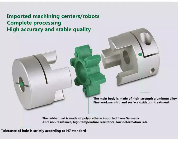
Helicoidal coupling
Helicoidal coupling is a form of nonlinear coupling between two molecules. It occurs when the molecules in a double helix are subjected to oscillations. These oscillations can occur either in the right or left-handed direction. These oscillations are called solitons. Helicoidal coupling can provide quantitative or qualitative support to a structure, such as an electron.
Split Muff coupling
The Split-Muff Coupling market report provides detailed market analysis and key insights. The study covers the market size, segmentation, growth and sales forecast. It also examines key factors driving the market growth and limiting its development. The report also covers current trends and vendor landscapes. Therefore, you can get a deep understanding of the Split-Muff Coupling industry and make the right business decisions.
The report also provides data on the competitive landscape and the latest product and technology innovations. It also provides information on market size, production and income. It also covers the impact of the COVID-19 regulations. The market report is a valuable resource for companies looking to expand their businesses, or to improve existing ones.
In terms of application, Split-Muff Couplings can be used in light to medium duty applications. They are shaped like a semi-cylindrical disc that fits over a shaft. Both parts are threaded for assembly and disassembly. It can be disassembled easily and quickly, and can be used for medium to heavy-duty applications with moderate speeds.
Split Muff couplings are the most popular type of couplings for transferring wet and abrasive materials. Their flanged end fits on most major brands of smooth material muff hoses. In addition, this type of coupling is corrosion-resistant and easy to install. It also does not require any adjustments to the drive shaft’s position.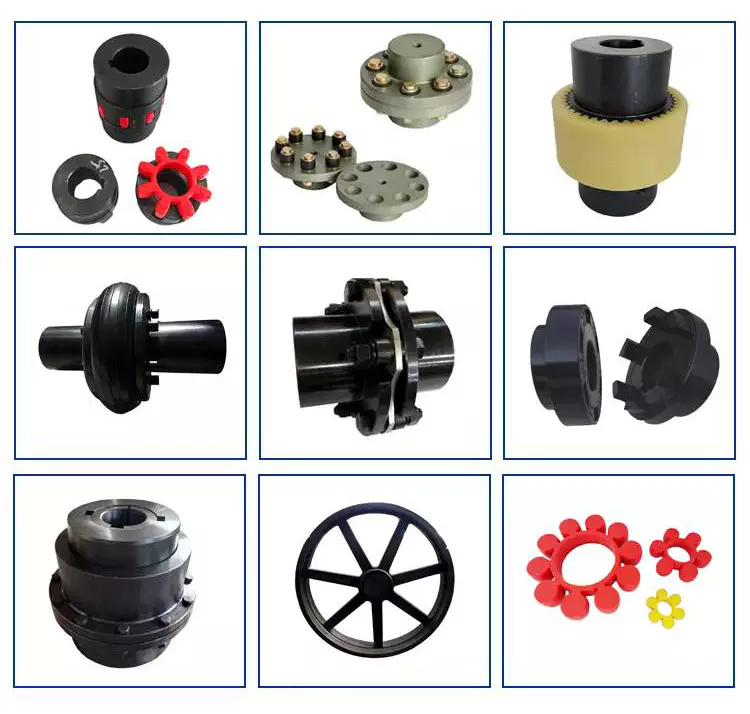
Flexible beam coupling
The Flexible beam coupling is one of the most popular types of couplings in the industry. It is comprised of two sets of parallel coils separated by a solid member, and it offers a wide range of torsional stiffness. These couplings are made of aluminum alloy or stainless steel. They offer excellent flexibility and are less expensive than many other types of couplings. They also require zero maintenance and can tolerate shaft misalignment.
Beam couplings are categorized into two types: helical and axial. The former is characterized by a high degree of flexibility, while the latter is used to compensate for higher misalignment. Both types are suitable for small torque applications and are available in a wide range of shaft sizes.
Flexible beam couplings are available in metric and US sizes, and feature a variety of options. They feature stainless steel or aluminum materials and are highly durable and corrosion-resistant. They also offer high torque capacities and excellent fatigue resistance. Flexible beam couplings are available with a wide range of options to meet your unique application needs.

editor by czh 2023-03-11
China CNC Motor Flexible Winding Shaft Coupling Aluminium Plum Flexible Shaft Coupling D25l30 Motor Connector Flexible Coupler coupling define
Guarantee: 3 years
Relevant Industries: Manufacturing Plant, Farms, Printing Outlets, Strength & Mining, Other, Automation Industrial, Manufacturing, 3D printer
Custom-made assist: OEM, ODM, OBM
Framework: Personalized
Adaptable or Rigid: Flexible
Common or Nonstandard: Nonstandard
Substance: Stainless Metal/Aluminium/etc
Product identify: Stepper motor flexible shaft coupling for encoder
Certificate: ISO9 14531413 14576326 14573559 14561970 14561971 we can provide create amount as your ask for well timed for that we have seventy three unit CNC equipment in our workshop. Our QC test crew use the adhering to resources to check out our create 100% and make certain of quality: vernier caliper, outdoors micrometer, 2nd/3D measurement, undertaking measurement, blue mild scan, plating thickness, hardness tester, salt spry device and so on, we can make precision as ,001mm! FAQ Q1. Are you a factory or trade business? We are manufacturing unit.Welcome to go to our manufacturing facility. Q2. What kind of generation provider do you provide?Mould making, die casting, CNC machining, stamping, plastic injection, assembly, and floor therapy. Q3. How about the direct time?Mildew: 3-5 weeksMass generation: 3-4 months This autumn. How about your top quality?♦We will make the procedure instruction once the sample is authorized. ♦We will 100% examine the merchandise just before shipment.♦Transactions can be by means of Alibaba’s trade assurance. Q5. How lengthy should we take for a quotation? Right after getting thorough information(your Second/3D drawings or samples), we will estimate you inside of 2 times.Q6. What is your quotation element?Drawings or Sample, Materials, End, and Amount.
Types of Couplings
A coupling is a device that connects two shafts together. It transmits power from one end to another and is used for joining rotating equipment. A coupling is flexible and can accommodate a certain amount of end movement and misalignment. This allows for more flexibility in applications. Various types of couplings are available, and each one serves a specific purpose.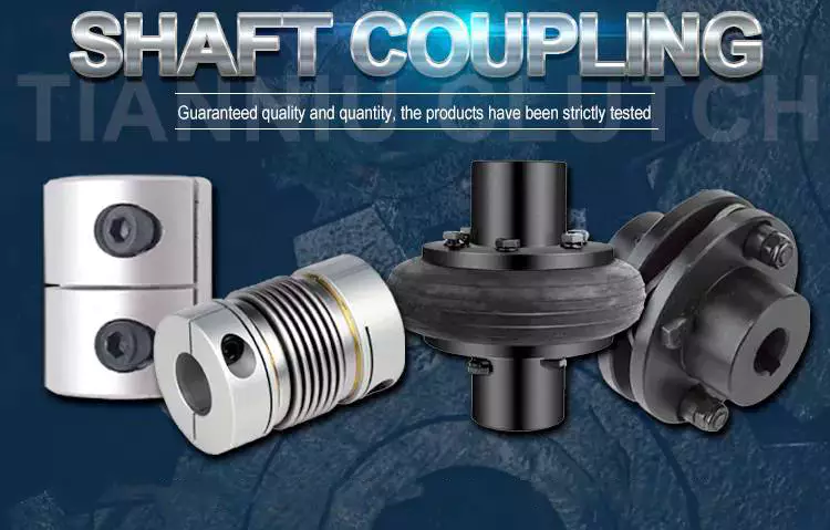
Shaft couplings
There are many types of shaft couplings, and they are used in a wide range of applications. The type you need depends on the torque, speed, and horsepower you need, as well as the size of the shaft and its spatial limitations. You may also need to consider whether the coupling will accommodate misalignment.
Some shaft couplings are flexible, while others are rigid. Flexible couplings can accommodate up to two degrees of misalignment. They are available in different materials, including aluminum, stainless steel, and titanium. They can also be known by different names, depending on the industry. Some couplings can also be used in a single or multiple-shaft application.
The first type of shaft coupling is a rigid coupling, which consists of two parts that fit together tightly around the shafts. These couplings are designed to have more flexibility than sleeved models, and they can be used on fixed shafts as well. The flanged coupling, on the other hand, is designed for heavy loads and is made of two perpendicular flanges. The flanges are large enough to accommodate screws and are generally used with heavy-duty applications.
CZPT shaft couplings are a great choice if you’re looking for a shaft coupling that delivers high performance, durability, and low cost. These metal disc-style couplings provide low backlash and high torsional stiffness. Their high misalignment tolerance reduces reaction loads on connected components, which makes them ideal for high-speed precision applications. Available in single and double-disc models, they have torque ratings of up to 2,200 in-lbs. (250N) and are available in fourteen sizes.
When using shaft couplings, it is important to choose the right type for your application. Backlash can cause a shaft coupling to break or become unusable. In order to prevent this from happening, you should replace worn or loose parts, and ensure that the hub and key are evenly positioned with the shaft. If you’re using a shaft coupling in a motion-control system, it is important to keep the torque level consistent.
Flexible couplings
Flexible couplings are a type of coupling used to connect two shafts. They are made of rubber or plastic and allow for axial movement of the connected equipment. They do not require lubrication and are resistant to fatigue failure. Flexible couplings are useful for a number of applications. A common type of flexible coupling is the gear coupling, which has gear teeth inside its sleeve. Another type of flexible coupling is the metallic membrane coupling. A metallic membrane coupling is flexible due to flexing metallic discs.
One major disadvantage of flexible couplings is their inability to fit certain types of pipe. This is because most couplings need to be stretched to fit the pipe. This problem is often the result of a change in pipe technology. Traditionally, drain and soil pipe is made of ductile iron or cast iron. Today, most pipes are made of PVC, which has a larger outside diameter than either cast or ductile iron. Because of these changes in pipe technology, many coupling manufacturers have not updated their mold sizing.
Flexible couplings can be either metallic, elastomeric, or a combination of the three. While there are some common characteristics of each type, you should always consider the tradeoffs of each type before choosing one. Generally, the most important considerations when selecting a flexible coupling are torque, misalignment, and ease of assembly and maintenance.
Flexible couplings are used in a wide range of industries. They are useful for connecting two pipes to ensure torque transfer. Although the types available are different, these are the most adaptable couplings in the market. They can withstand movement, vibration, and bending without causing any damage to the piping.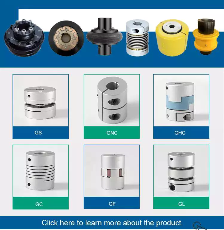
Clutch couplings
A clutch coupling connects two rotating shafts by friction. The clutch engages power when the engine is running, disengaging power when the brake is applied. Clutch couplings are used in applications where the speed of a machine is variable or where continuous service is required. The clutch can transmit power, torque, and axial force.
Clutch couplings come in a variety of styles and configurations. Some couplings are flexible, while others are rigid. Flexible couplings are available in a variety of materials, including stainless steel and aluminum. Some couplings also have a non-backlash design, which helps compensate for misalignment.
Clutch couplings may be synchronous or asynchronous. Synchronous couplings engage and disengage automatically when the driven machine exceeds its output speed. These couplings are synchronized by a synchronizing mechanism. When the output speed is exceeded, the synchronizing mechanism initiates the engagement process. The synchronizing mechanism does not engage or disengage when the output speed drops.
High speed clutches are available from a variety of manufacturers. Some manufacturers offer OEM assembly, repair services, and third-party logistics. These manufacturers serve the automotive, chemical, food, and wood industries, as well as the oilfield and material handling industries. Custom clutches can be manufactured for specific applications and can be fitted with additional features, such as precision machined teeth or keyway slots and grooves.
Couplings are available in PCE, C/T, and metric bores. Typically, the size of the input and output shafts will determine which type of coupling is needed. In addition, clutches may be configured for intermediate or high speeds, depending on the required torque.
Clamped couplings
Clamped couplings are commonly used in a variety of industries. They can be used in medical equipment, dental equipment, military equipment, laboratory equipment, and in precision industrial controls. They are available in a wide variety of sizes and keyways. This type of coupling offers a number of advantages, including ease of installation and quick and easy replacement.
A clamp coupling connects two parts by compressing them together. The clamping elements can be formed in a variety of ways, but they all have a gap between their surfaces. This friction squeezes the two parts together, much like pulling two rubber gloves apart. This type of coupling is also useful for joining two hoses or piping units.
Clamped couplings are designed with a single or double clamping shaft. The clamping parts are mounted in two halves and are held together by eight socket head cap screws. They offer high torque capacity and require little installation space. Their high rigidity ensures good positioning accuracy, making them ideal for dynamic drives. In addition, they are wear-free and offer simple radial assembly.
The invention relates to a method and system for clamping pipes to a tank vessel. This invention also relates to a method of loading and unloading tank vessels. The method can be used in oil production platforms and other platforms. A single point mooring method is also used in oil production platforms.
Clamped couplings can also be flexible. They can join two shafts together while allowing a small amount of end movement and misalignment. These couplings may also be used in the assembly of motors and gearboxes.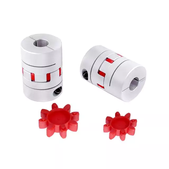
CZPT’s coupling
CZPT couplings are designed to be flexible, allowing them to accommodate misaligned shafts and transmit torque in either direction. They are made with three discs, two hubs, and a center that are arranged with grooves and fins. These features allow for two degrees of freedom during assembly, and can accommodate misalignment of up to 5% of the shaft diameter.
CZPT couplings have many uses. For example, they can be used to join two parallel coaxial rotating shafts. Their ability to transmit torque at the same rotation mechanism and speed makes them ideal for applications where electrical currents may be a problem. Because the couplings are not made of metal, they are electrically isolated. Designers should test their couplings during the prototype stage to ensure they are working properly.
The CZPT coupling consists of two hubs with one slot on each. An intermediate disk is located between the two hubs. The discs are used to reduce or prevent wear on other machine parts. CZPT couplings are inexpensive and easy to replace. They also have electrical insulation, which makes them easy to repair or replace.
CZPT couplings are a popular choice for stepper motor-driven positioning stages. The plastic center disc offers electrical isolation and absorbs shocks from frequent start/stops. These couplings are available in through-hub and blind-bore styles and can be installed in many applications.
CZPT couplings also allow for small degrees of shaft misalignment. This allows them to function in systems where shaft access is limited. They are easily removed without tools.

editor by czh 2023-02-24
China China CNC Electric Motor Steel Coupling Gear Shaft Coupling Shafts coupling constant
Composition: Worm
Content: Stainless metal, Aluminum, copper, brass, stainless metal, Carbon steel or OEM
Coatings: Aluminum, brass, stainless steel, steel, iron, alloy, zinc etc.
Torque Capacity: Custom made-Producing
Duration: Request
Design Amount: gear shaft coupling
Name: gear shaft coupling
Tolerance: ±0.01mm-.
Internet:
Skype: CZPT 0571
Insert:No.39 Jingfu West Road ,Yangkengtang Village,DalangTown,HangZhou,ZheJiang , CZPT S sequence equivalent SC right – angle planetary equipment device China
Types of Couplings
A coupling is a device that connects two shafts and transmits power from one to the other. Its main purpose is to join two pieces of rotating equipment. It also allows for some degree of misalignment or end movement. Here are a few examples of coupling types: Beam coupling, Flexible coupling, Magnetic coupling, and Shaft coupling.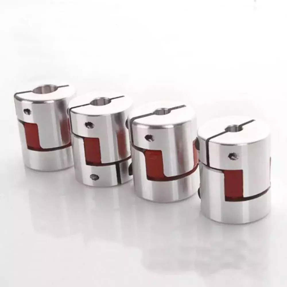
Beam coupling
Beam couplings are used to couple motors and other devices. They are available in several types, including flexible, slit, and rigid beam couplings. Each has unique properties and characteristics. These couplings are best for applications requiring a high level of precision and long life. They are also a practical solution for the connection of stepping and servo motors with screw rods.
Beam couplings are usually made of stainless steel or aluminum alloy, and feature spiral and parallel cut designs. Multiple cuts allow the coupling to accommodate multiple beams and improve angular and parallel misalignment tolerances. Additionally, beam couplings are comparatively cheaper than other types of rotary joints, and they require minimal maintenance.
The materials of a beam coupling should be considered early in the specification process. They are typically made of aluminum or stainless steel, but they can also be manufactured from Delrin, titanium, and other engineering grade materials. Beam couplings are often available in multiple sizes to fit specific shaft diameters.
Beam couplings are a key component of motion control systems. They provide excellent characteristics when used properly, and they are a popular choice for many applications. A thorough understanding of each type of coupling will help to prevent coupling failure and enhance system performance. Therefore, it is important to choose the right coupling for your application.
Various types of beam couplings have unique advantages and disadvantages. The FCR/FSR design has two sets of three beams. It is available in both metric and inch shaft sizes. The FCR/FSR couplings are ideal for light-duty power transmission applications. A metric shaft is more suitable for these applications, while an inch shaft is preferred for heavier duty applications.
Two types of beam couplings are available from Ruland. The Ruland Flexible beam coupling has a multi-helical cut design that offers a greater flexibility than commodity beam couplings. This design allows for higher torque capabilities while minimizing wind-up. In addition, it is also more durable than its commodity counterparts.
Flexible coupling
A flexible coupling is a versatile mechanical connection that allows for the easy coupling of two moving parts. The design of these couplings allows for a variety of stiffness levels and can address a variety of problems, such as torsional vibrations or critical speed. However, there are a number of tradeoffs associated with flexible couplings.
One of the biggest issues is the installation of the coupling, which requires stretching. This problem can be exacerbated by cold temperatures. In such a case, it is vital to install the coupling properly. Using a gear clamp is one of the most important steps in a successful installation. A gear clamp will keep the coupling in place and prevent it from leaking.
Another common type of flexible coupling is the gear coupling. These couplings are composed of two hubs with crowned external gear teeth that mesh with two internally splined flanged sleeves. The massive size of the teeth makes them resemble gears. Gear couplings offer good torque characteristics but require periodic lubrication. These couplings can also be expensive and have a limited number of applications.
Another type of flexible coupling is the SDP/SI helical coupling. These couplings can accommodate axial motion, angular misalignment, and parallel offset. This design incorporates a spiral pattern that makes them flexible. These couplings are available in stainless steel and aluminum.
A flexible coupling has a wide range of applications. Generally, it is used to connect two rotating pieces of equipment. Depending on its design, it can be used to join two pieces of machinery that move in different directions. This type of coupling is a type of elastomeric coupling, which has elastic properties.
There are many types of flexible couplings available for different types of applications. The purpose of a flexible coupling is to transmit rotational power from one shaft to another. It is also useful for transmitting torque. However, it is important to note that not all flexible couplings are created equally. Make sure to use a reputable brand for your coupling needs. It will ensure a reliable connection.
The simplest and most commonly used type of flexible coupling is the grid coupling. This type of coupling uses two hubs with slotted surfaces. The steel grid is allowed to slide along these slots, which gives it the ability to flex. The only limitation of this type of coupling is that it can only tolerate a 1/3 degree misalignment. It can transmit torques up to 3,656 Nm.
Magnetic coupling
Magnetic coupling is a technique used to transfer torque from one shaft to another using a magnetic field. It is the most common type of coupling used in machinery. It is highly effective when transferring torque from a rotating motor to a rotating shaft. Magnetic couplings can handle high torques and high speeds.
Magnetic coupling is described by the energy difference between a high-spin state and a broken symmetry state, with the former being the energy of a true singlet state. In single-determinant theories, this energy difference is called the Kij. Usually, the broken-symmetry state is a state with two interacting local high-spin centers.
The magnetic coupling device is regarded as a qualitative leap in the reaction still industry. It has solved a number of problems that had plagued the industry, including flammability, explosiveness, and leakage. Magnetic couplings are a great solution for many applications. The chemical and pharmaceutical industries use them for various processes, including reaction stills.
Magnetic couplings are a good choice for harsh environments and for tight spaces. Their enclosed design keeps them fluid and dust-proof. They are also corrosion-resistant. In addition, magnetic couplings are more affordable than mechanical couplings, especially in areas where access is restricted. They are also popular for testing and temporary installations.
Another use for magnetic coupling is in touch screens. While touch screens use capacitive and resistive elements, magnetic coupling has found a cool new application in wireless charging. While the finger tracking on touch screens may seem like a boley job, the process is very sensitive. The devices that use wireless charging need to have very large coils that are locked into resonant magnetic coupling.
Magnetic couplings also help reduce hydraulic horsepower. They cushion starts and reduce alignment problems. They can also improve flow in oversized pumps. A magnetic coupling with an 8 percent air gap can reduce hydraulic HP by approximately 27 percent. In addition, they can be used in aggressive environments. They also help reduce repair costs.
Magnetic couplings are a great choice for pumps and propeller systems because they have the added advantage of being watertight and preventing shaft failure. These systems also have the benefit of not requiring rotating seals.
Shaft coupling
A shaft coupling joins two shafts and transmits rotational motion. Generally, shaft couplings allow for some degree of misalignment, but there are also torque limiters. Selecting the right coupling can save you time and money and prevent equipment downtime. Here are the main features to consider when purchasing a coupling for your application.
Shaft couplings should be easy to install and disassemble, transmit full power to the mated shaft, and reduce shock loads. A shaft coupling that does not have projecting parts should be used for machines that move or rotate at high speeds. Some types of shaft couplings are flexible while others are rigid.
Shaft couplings can be used in a variety of applications, including piping systems. They can be used to connect shafts that are misaligned and help maintain alignment. They can also be used for vibration dampening. Shaft couplings also allow shafts to be disconnected when necessary.
Shaft couplings can accommodate a certain amount of backlash, but this backlash must be well within the tolerance set by the system. Extremely high backlash can break the coupling and cause excessive wear and stress. In addition, excessive backlash can lead to erratic alignment readings. To avoid these issues, operators must reduce backlash to less than 2deg.
Shaft couplings are often referred to by different names. Some are referred to as “sliced” couplings while others are known as “slit” couplings. Both types offer high torque and torsional stiffness. These couplings are typically made from metals with various alloys, such as acetal, stainless steel, or titanium.
CZPT Pulley produces shaft couplings for a variety of applications. These products are used in high-power transmission systems. They have several advantages over friction couplings. In addition to minimizing wear, they don’t require lubrication. They are also capable of transmitting high torque and high speeds.
Another type of shaft coupling is the universal coupling. It is used to transmit power to multiple machines with different spindles. Its keyed receiving side and flanges allow it to transmit power from one machine to another.

editor by czh 2023-02-22
China Standard Twotrees CNC Motor Jaw Shaft Coupler 6mm to 8mm Flexible Coupling flexible coupling
Relevant Industries: Manufacturing Plant, Machinery Fix Shops, Printing Shops, Other
Tailored assist: OEM, ODM
Construction: Common
Versatile or Rigid: Rigid
Common or Nonstandard: Common
Materials: Stainless metal
Port: shenshen
Courier edge Business Profile ShenZhen TwoTrees Engineering Co.,Ltd is a one particular-cease service supplier for 3D print creation, R&D, revenue, accessories and 3D print-connected derivatives.we concentrate on study and develop new technological innovation to produce new products.Supply successful and affordable 3D printing remedies for folks, families, education and enterprises.Meet each customer’s demands for effectiveness, high quality and fast prototyping.The company is positioned in HangZhou, and cooperates with a quantity of institutions of higher studying to build an business-college investigation and training exercise foundation for analysis and development, producing, soon after-income and other sequence. The firm handles an region of practically 2,000 square meters, with advanced massive-scale study and growth centers and 3D printing laboratories. The contemporary manufacturing line, with each other with 4 24 hour uninterrupted specialist check lines and stringent quality management method, ensures merchandise top quality from the source.
What You Should Know About Axle Shafts
There are several things you should know about axle shafts. These include what materials they’re made of, how they’re constructed, and the signs of wear and tear. Read on to learn more about axle shafts and how to properly maintain them. Axle shafts are a crucial part of any vehicle. But how can you tell if one is worn out? Here are some tips that can help you determine whether it’s time to replace it.
Materials used for axle shafts
When it comes to materials used in axle shafts, there are two common types of materials. One is carbon fiber, which is relatively uncommon for linear applications. Carbon fiber shafting is produced by CZPT(r). The main benefit of carbon fiber shafting is its ultra-low weight. A carbon fiber shaft of 20mm diameter weighs just 0.17kg, as opposed to 2.46kg for a steel shaft of the same size.
The other type of material used in axle shafts is forged steel. This material is strong, but it is difficult to machine. The resulting material has residual stresses, voids, and hard spots that make it unsuitable for some applications. A forged steel shaft will not be able to be refinished to its original dimensions. In such cases, the shaft must be machined down to reduce the material’s hardness.
Alternatively, you can choose to purchase a through-hardened shaft. These types of axle shafts are suitable for light cars and those that use single bearings on their hub. However, the increased diameter of the axle shaft will result in less resistance to shock loads and torsional forces. For these applications, it is best to use medium-carbon alloy steel (MCA), which contains nickel and chromium. In addition, you may also need to jack up your vehicle to replace the axle shaft.
The spline features of the axle shaft must mate with the spline feature on the axle assembly. The spline feature has a slight curve that optimizes contact surface area and distribution of load. The process involves hobbing and rolling, and it requires special tooling to form this profile. However, it is important to note that an axle shaft with a cut spline will have a 30% smaller diameter than the corresponding one with an involute profile.
Another common material is the 300M alloy, which is a modified 4340 chromoly. This alloy provides additional strength, but is more prone to cracking. For this reason, this alloy isn’t suited for street-driven vehicles. Axle shafts made from this alloy are magnaflushed to detect cracks before they cause catastrophic failure. This heat treatment is not as effective as the other materials, but it is still a good choice for axle shafts.
Construction
There are three basic types of axle shafts: fully floating, three-quarter floating, and semi-floating. Depending on how the shaft is used, the axles can be either stationary or fully floating. Fully floating axle shafts are most common, but there are exceptions. Axle shafts may also be floating or stationary, or they may be fixed. When they are stationary, they are known as non-floating axles.
Different alloys have different properties. High-carbon steels are harder than low-carbon steels, while medium-carbon steels are less ductile. Medium-carbon steel is often used in axle shafts. Some shafts contain additional metals, including silicon, nickel, and copper, for case hardening. High-carbon steels are preferred over low-carbon steels. Axle shafts with high carbon content often have better heat-treatability than OE ones.
A semi-floating axle shaft has a single bearing between the hub and casing, relieving the main shear stress on the shaft but must still withstand other stresses. A half shaft needs to withstand bending loads from side thrust during cornering while transmitting driving torque. A three-quarter floating axle shaft is typically fitted to commercial vehicles that are more capable of handling higher axle loads and torque. However, it is possible to replace or upgrade the axle shaft with a replacement axle shaft, but this will require jacking the vehicle and removing the studs.
A half-floating axle is an alternative to a fixed-length rear axle. This axle design is ideal for mid-size trucks. It supports the weight of the mid-size truck and may support mid-size trucks with high towing capacities. The axle housing supports the inner end of the axle and also takes up the end thrust from the vehicle’s tires. A three-quarter floating axle, on the other hand, is a complex type that is not as simple as a semi-floating axle.
Axle shafts are heavy-duty load-bearing components that transmit rotational force from the rear differential gearbox to the rear wheels. The half shaft and the axle casing support the road wheel. Below is a diagram of different forces that can occur in the axle assembly depending on operating conditions. The total weight of the vehicle’s rear can exert a bending action on the half shaft, and the overhanging section of the shaft can be subject to a shearing force.
Symptoms of wear out
The constant velocity axle, also called the half shaft, transmits power from the transmission to the wheels, allowing the vehicle to move forward. When it fails, it can result in many problems. Here are four common symptoms of a bad CV axle:
Bad vibrations: If you notice any sort of abnormal vibration while driving, this may be a sign of axle damage. Vibrations may accompany a strange noise coming from under the vehicle. You may also notice tire wobble. It is important to repair this problem as it could be harmful to your car’s handling and comfort. A damaged axle is generally accompanied by other problems, including a weak braking response.
A creaking or popping sound: If you hear this noise when turning your vehicle, you probably have a worn out CV axle. When the CV joints lose their balance, the driveshaft is no longer supported by the U-joints. This can cause a lot of vibrations, which can reduce your vehicle’s comfort and safety. Fortunately, there are easy ways to check for worn CV axles.
CV joints: A CV joint is located at each end of the axle shaft. In front-wheel drive vehicles, there are two CV joints, one on each axle. The outer CV joint connects the axle shaft to the wheel and experiences more movement. In fact, the CV joints are only as good as the boot. The most common symptoms of a failed CV joint include clicking and popping noises while turning or when accelerating.
CV joint: Oftentimes, CV joints wear out half of the axle shaft. While repairing a CV joint is a viable repair, it is more expensive than replacing the axle. In most cases, you should replace the CV joint. Replacement will save you time and money. ACV joints are a vital part of your vehicle’s drivetrain. Even if they are worn, they should be checked if they are loose.
Unresponsive acceleration: The vehicle may be jerky, shuddering, or slipping. This could be caused by a bent axle. The problem may be a loose U-joint or center bearing, and you should have your vehicle inspected immediately by a qualified mechanic. If you notice jerkiness, have a mechanic check the CV joints and other components of the vehicle. If these components are not working properly, the vehicle may be dangerous.
Maintenance
There are several points of concern regarding the maintenance of axle shafts. It is imperative to check the axle for any damage and to lubricate it. If it is clean, it may be lubricated and is working properly. If not, it will require replacement. The CV boots need to be replaced. A broken axle shaft can result in catastrophic damage to the transmission or even cause an accident. Fortunately, there are several simple ways to maintain the axle shaft.
In addition to oil changes, it is important to check the differential lube level. Some differentials need cleaning or repacking every so often. CZPT Moreno Valley, CA technicians know how to inspect and maintain axles, and they can help you determine if a problem is affecting your vehicle’s performance. Some common signs of axle problems include excessive vibrations, clunking, and a high-pitched howling noise.
If you’ve noticed any of these warning signs, contact your vehicle’s manufacturer. Most manufacturers offer service for their axles. If it’s too rusted or damaged, they’ll replace it for you for free. If you’re in doubt, you can take it to a service center for a repair. They’ll be happy to assist you in any aspect of your vehicle’s maintenance. It’s never too early to begin.
CZPT Moreno Valley, CA technicians are well-versed in the repair of axles and differentials. The CV joint, which connects the car’s transmission to the rear wheels, is responsible for transferring the power from the engine to the wheels. Aside from the CV joint, there are also protective boots on both ends of the axle shaft. The protective boots can tear with age or use. When they tear, they allow grease and debris to escape and get into the joint.
While the CV joint is the most obvious place to replace it, this isn’t a time to ignore this important component. Taking care of the CV joint will protect your car from costly breakdowns at the track. While servicing half shafts can help prevent costly replacement of CV joints, it’s best to do it once a season or halfway through the season. ACV joints are essential for your car’s safety and function.


editor by czh
China Professional rongde unique high seal compact duty aluminium cnc stainless steel connect shaft helical flexible standard coupling flange coupling
Relevant Industries: Restaurant, Foodstuff Shop, Development works , Power & Mining, Marketing Firm
Composition: Jaw / Spider
Versatile or Rigid: Versatile
Standard or Nonstandard: Regular
Substance: Aluminium
Certification: CE & ISO9001
Outdoors diameter(D): 16-51mm
Duration: 22-51mm
standard bore: 3-25mm
rated torque: .4-14N
Max torque: .8-28N
Angular misalignment: 3
Max rotational velocity: 6000r/min
Packaging Particulars: Carton
Port: HangZhou
rongde exclusive substantial seal compact obligation aluminium cnc stainless metal connect shaft helical versatile common coupling
Adaptable couplings are utilized to transmit torque from 1 shaft to one more when the 2 shafts are a bit misaligned. It can accommodate different degrees of misalignment up to 3°. In addition to allowing for misalignment, it can also be utilised for vibration damping or sound reduction.Encoder couplings, adaptable coupling, couplings doing work with Encoder & all kinds of motors (servo motor, DC motor, AC motor, equipment motors).
Solution Pictures
Much more Items
Merchandise Testing
Packaing & Transport
Business Introduction
HangZhou CZPT Optics Co., Ltd. is located in the present day metropolis- Changhun which is know as the optoelectronics market base of China. Specializing in the creation of rotary encoders and other industrial automation sensor-connected goods, merchandise employed in pace measurement, angle measurement, duration measurement. To improve the company’s product sales and following-product sales community, we established up branch firm in ZheJiang , HangZhou, Xi’an, HangZhou and ZheJiang and many others.
*Exceptional top quality: professional R&D staff, stringent top quality screening.*Speedy response: an in depth income network to ensure timely and successful interaction.*Power to ensure: sufficient stock, the shortest guide time.*Tailored services: to meet up with the a variety of of needs from consumers.Right after-income service: merchandise warranty period of eighteen months.
The Exhibition And Photographs
Certificate
Our Service
1. The inquiries about the encoder will be answered within 24 hours.
two. A single-quit remedy will supply to meet all your needs on price range, developing and shipment.
three. We can offer you the information of supplier in your market if you want to make contact with them right.
4. Update the procession of producing.
five. Warranty eighteen months: Cost-free substitute of faulty goods inside of 18 months.
FAQ
Q1:Can I have a sample for screening?
A: Truly we have a quite very good price basic principle, when you make the bulk purchase then value of sample will be return to you. The price is the very same for fifty-one hundred sets which includes the sample
Q2:Can I insert my symbol on the encoder ?
A:Indeed,OEM and ODM are available for us. But you should ship us the Trademark authorization letter.
Q3:How can i get the right after-service?
A:We will send out you the spare parts by cost-free if the issues induced by us. If it is the men-produced difficulties,we also ship the spare areas,but you ought to pay out. For our variety hood motors it is lifelong servicing.
Q4 :Do you have inspection processes for encoder ?
A:100% self-inspection prior to packing
Q5:Can I have a pay a visit to to your manufacturing unit ahead of the order?
A: Certain,welcome to go to our manufacturing unit.
Listed here is our manufacturing facility handle: No.1666, Ya’an Street, Xihu (West Lake) Dis. District, Chanchun, China
We can select you up in the airport.
Make contact with US More detail info, welcome to pay a visit to our web site: .cn
An Overview of Worm Shafts and Gears
This article provides an overview of worm shafts and gears, including the type of toothing and deflection they experience. Other topics covered include the use of aluminum versus bronze worm shafts, calculating worm shaft deflection and lubrication. A thorough understanding of these issues will help you to design better gearboxes and other worm gear mechanisms. For further information, please visit the related websites. We also hope that you will find this article informative.
Double throat worm gears
The pitch diameter of a worm and the pitch of its worm wheel must be equal. The two types of worm gears have the same pitch diameter, but the difference lies in their axial and circular pitches. The pitch diameter is the distance between the worm’s teeth along its axis and the pitch diameter of the larger gear. Worms are made with left-handed or right-handed threads. The lead of the worm is the distance a point on the thread travels during one revolution of the worm gear. The backlash measurement should be made in a few different places on the gear wheel, as a large amount of backlash implies tooth spacing.
A double-throat worm gear is designed for high-load applications. It provides the tightest connection between worm and gear. It is crucial to mount a worm gear assembly correctly. The keyway design requires several points of contact, which block shaft rotation and help transfer torque to the gear. After determining the location of the keyway, a hole is drilled into the hub, which is then screwed into the gear.
The dual-threaded design of worm gears allows them to withstand heavy loads without slipping or tearing out of the worm. A double-throat worm gear provides the tightest connection between worm and gear, and is therefore ideal for hoisting applications. The self-locking nature of the worm gear is another advantage. If the worm gears are designed well, they are excellent for reducing speeds, as they are self-locking.
When choosing a worm, the number of threads that a worm has is critical. Thread starts determine the reduction ratio of a pair, so the higher the threads, the greater the ratio. The same is true for the worm helix angles, which can be one, two, or three threads long. This varies between a single thread and a double-throat worm gear, and it is crucial to consider the helix angle when selecting a worm.
Double-throat worm gears differ in their profile from the actual gear. Double-throat worm gears are especially useful in applications where noise is an issue. In addition to their low noise, worm gears can absorb shock loads. A double-throat worm gear is also a popular choice for many different types of applications. These gears are also commonly used for hoisting equipment. Its tooth profile is different from that of the actual gear.
Bronze or aluminum worm shafts
When selecting a worm, a few things should be kept in mind. The material of the shaft should be either bronze or aluminum. The worm itself is the primary component, but there are also addendum gears that are available. The total number of teeth on both the worm and the addendum gear should be greater than forty. The axial pitch of the worm needs to match the circular pitch of the larger gear.
The most common material used for worm gears is bronze because of its desirable mechanical properties. Bronze is a broad term referring to various copper alloys, including copper-nickel and copper-aluminum. Bronze is most commonly created by alloying copper with tin and aluminum. In some cases, this combination creates brass, which is a similar metal to bronze. The latter is less expensive and suitable for light loads.
There are many benefits to bronze worm gears. They are strong and durable, and they offer excellent wear-resistance. In contrast to steel worms, bronze worm gears are quieter than their counterparts. They also require no lubrication and are corrosion-resistant. Bronze worms are popular with small, light-weight machines, as they are easy to maintain. You can read more about worm gears in CZPT’s CZPT.
Although bronze or aluminum worm shafts are the most common, both materials are equally suitable for a variety of applications. A bronze shaft is often called bronze but may actually be brass. Historically, worm gears were made of SAE 65 gear bronze. However, newer materials have been introduced. SAE 65 gear bronze (UNS C90700) remains the preferred material. For high-volume applications, the material savings can be considerable.
Both types of worms are essentially the same in size and shape, but the lead on the left and right tooth surfaces can vary. This allows for precise adjustment of the backlash on a worm without changing the center distance between the worm gear. The different sizes of worms also make them easier to manufacture and maintain. But if you want an especially small worm for an industrial application, you should consider bronze or aluminum.
Calculation of worm shaft deflection
The centre-line distance of a worm gear and the number of worm teeth play a crucial role in the deflection of the rotor. These parameters should be entered into the tool in the same units as the main calculation. The selected variant is then transferred to the main calculation. The deflection of the worm gear can be calculated from the angle at which the worm teeth shrink. The following calculation is helpful for designing a worm gear.
Worm gears are widely used in industrial applications due to their high transmittable torques and large gear ratios. Their hard/soft material combination makes them ideally suited for a wide range of applications. The worm shaft is typically made of case-hardened steel, and the worm wheel is fabricated from a copper-tin-bronze alloy. In most cases, the wheel is the area of contact with the gear. Worm gears also have a low deflection, as high shaft deflection can affect the transmission accuracy and increase wear.
Another method for determining worm shaft deflection is to use the tooth-dependent bending stiffness of a worm gear’s toothing. By calculating the stiffness of the individual sections of a worm shaft, the stiffness of the entire worm can be determined. The approximate tooth area is shown in figure 5.
Another way to calculate worm shaft deflection is by using the FEM method. The simulation tool uses an analytical model of the worm gear shaft to determine the deflection of the worm. It is based on a two-dimensional model, which is more suitable for simulation. Then, you need to input the worm gear’s pitch angle and the toothing to calculate the maximum deflection.
Lubrication of worm shafts
In order to protect the gears, worm drives require lubricants that offer excellent anti-wear protection, high oxidation resistance, and low friction. While mineral oil lubricants are widely used, synthetic base oils have better performance characteristics and lower operating temperatures. The Arrhenius Rate Rule states that chemical reactions double every ten degrees C. Synthetic lubricants are the best choice for these applications.
Synthetics and compounded mineral oils are the most popular lubricants for worm gears. These oils are formulated with mineral basestock and four to six percent synthetic fatty acid. Surface-active additives give compounded gear oils outstanding lubricity and prevent sliding wear. These oils are suited for high-speed applications, including worm gears. However, synthetic oil has the disadvantage of being incompatible with polycarbonate and some paints.
Synthetic lubricants are expensive, but they can increase worm gear efficiency and operating life. Synthetic lubricants typically fall into two categories: PAO synthetic oils and EP synthetic oils. The latter has a higher viscosity index and can be used at a range of temperatures. Synthetic lubricants often contain anti-wear additives and EP (anti-wear).
Worm gears are frequently mounted over or under the gearbox. The proper lubrication is essential to ensure the correct mounting and operation. Oftentimes, inadequate lubrication can cause the unit to fail sooner than expected. Because of this, a technician may not make a connection between the lack of lube and the failure of the unit. It is important to follow the manufacturer’s recommendations and use high-quality lubricant for your gearbox.
Worm drives reduce backlash by minimizing the play between gear teeth. Backlash can cause damage if unbalanced forces are introduced. Worm drives are lightweight and durable because they have minimal moving parts. In addition, worm drives are low-noise and vibration. In addition, their sliding motion scrapes away excess lubricant. The constant sliding action generates a high amount of heat, which is why superior lubrication is critical.
Oils with a high film strength and excellent adhesion are ideal for lubrication of worm gears. Some of these oils contain sulfur, which can etch a bronze gear. In order to avoid this, it is imperative to use a lubricant that has high film strength and prevents asperities from welding. The ideal lubricant for worm gears is one that provides excellent film strength and does not contain sulfur.


editor by czh