Product Description
Flexible Flange OEM Low-End Hydraulic Quick Release UL Black Rubber Ring Shaft Pumps Elastic Tyre Coupling for Motor
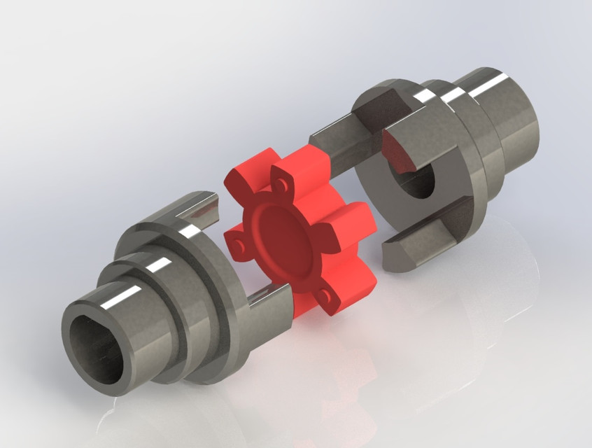
Product Name: type tire coupling Surface treatment: phosphating, blackening and spraying Coupling type: tire coupling Material: Rubber Scope of application: metallurgy, steel rolling, mining, chemical industry, shipbuilding, pumps, fans, etc. Features: the tire coupling has good shock absorption and buffering effect and the performance of compensating the deviation between axles. It is widely used in the occasions of impact vibration, variable CHINAMFG and reverse rotation and frequent starting.
Related products:
Production workshop:
Company information:
/* January 22, 2571 19:08:37 */!function(){function s(e,r){var a,o={};try{e&&e.split(“,”).forEach(function(e,t){e&&(a=e.match(/(.*?):(.*)$/))&&1
Compensation for Misalignment in Elastic Couplings
Elastic couplings are designed to accommodate certain degrees of misalignment between connected components in mechanical systems. The elastomeric material used in the coupling plays a crucial role in this compensation process:
When the two components connected by the elastic coupling experience angular, parallel, or axial misalignment, the elastomeric material deforms to a certain extent. This deformation allows the coupling to maintain its connection while absorbing the misalignment-induced stresses and forces.
The elastomer acts as a flexible link between the components, allowing them to move relative to each other within specified limits. The deformation of the elastomer also helps distribute the load more evenly, reducing stress concentrations and the risk of premature wear or damage to the coupling or connected components.
Elastic couplings can compensate for both static and dynamic misalignment, making them suitable for applications where minor misalignment is unavoidable due to factors such as manufacturing tolerances, thermal expansion, or vibration.
It’s important to note that while elastic couplings can accommodate misalignment, excessive misalignment should still be avoided, as it can lead to accelerated wear and reduced coupling lifespan. Regular inspection and maintenance are recommended to ensure that the coupling is operating within its designed limits.
Advancements in Elastic Coupling Technology
Recent advancements in elastic coupling technology have led to improved performance and capabilities. Some notable developments include:
- Enhanced Materials: The use of advanced materials, such as high-performance elastomers and composites, has resulted in elastic couplings that offer higher strength, durability, and resistance to wear and fatigue.
- Optimized Designs: Engineers are employing advanced computer simulations and modeling techniques to optimize the design of elastic couplings. This has led to designs that provide better torsional flexibility, reduced backlash, and improved performance in demanding conditions.
- Vibration Dampening: Advancements in elastic coupling technology have focused on improving vibration dampening properties. This is particularly important in applications where minimizing vibration and shock is crucial for the machinery’s precision and longevity.
- Customization: Modern elastic coupling manufacturers offer more options for customization, allowing engineers to select the best coupling configuration, size, and material for their specific application requirements.
- Smart Couplings: Some elastic couplings now incorporate sensors and monitoring technology to provide real-time data on coupling performance, misalignment, and wear. This data can aid in predictive maintenance and enhance overall system reliability.
These advancements in elastic coupling technology continue to contribute to the efficiency, reliability, and overall performance of machinery systems in various industries.
Factors to Consider When Selecting an Elastic Coupling
Engineers must carefully evaluate several factors when selecting an appropriate elastic coupling for a specific application. These factors ensure that the coupling can effectively meet the requirements of the machinery and system:
- Torque Transmission: Consider the amount of torque that needs to be transmitted between the connected shafts. Ensure that the coupling’s torque rating matches or exceeds the application’s torque requirements.
- Misalignment Compensation: Evaluate the expected misalignments between the shafts, such as angular, parallel, and axial misalignments. Choose a coupling with the appropriate flexibility and misalignment capacity to accommodate these variations.
- Vibration Dampening: Determine the level of vibration present in the system and select a coupling with the necessary torsional elasticity to dampen vibrations and provide smoother operation.
- Operating Speed: Consider the rotational speed of the connected shafts. Some elastic couplings may have speed limitations, so choose a coupling that can handle the desired operating speed without issues.
- Environmental Conditions: Assess the operating environment, including temperature, humidity, and the presence of contaminants. Choose a coupling material that can withstand the conditions and resist corrosion or degradation.
- Space Limitations: Take into account the available space for installing the coupling. Some couplings may have compact designs that are better suited for confined spaces.
- Shaft Sizes: Ensure that the coupling is compatible with the diameters of the connected shafts. Verify the coupling’s bore sizes and choose one that matches the shaft sizes.
- Installation and Maintenance: Consider the ease of installation and maintenance. Some couplings have simpler installation procedures, while others might require more complex procedures.
- Cost: Evaluate the budget for the coupling. While high-performance couplings might have added benefits, they could also come at a higher cost. Balance the performance requirements with budget constraints.
By carefully assessing these factors and selecting the appropriate elastic coupling, engineers can ensure optimal performance, longevity, and reliability of the machinery and systems they design.


editor by CX 2024-04-10
China supplier Hl Type Flexible Muff Flange Bush Flexible Elastic Sleeve Oldham Steel Disc Clamp Shaft Rigid FCL Pin Coupling with Brake Wheel
Product Description
Hl Type Flexible Muff Flange Bush Flexible Elastic Sleeve Oldham Steel Disc Clamp Shaft Rigid Fcl Pin Coupling With Brake WHEEL
The characteristics of FCL Flexible Pin & Bush Coupling
(1)Coupling is simple in structure, convenient installation, easy replacement, small size, light weight.
(2)If the installation adjustment can keep 2 relative displacement within the prescribed limits, then coupling will have satisfactory performance and long service life.
(3) It can be widely applied to all kinds of medium and small power transmission shafts, such as reducer, crane, compressor, conveyor, textile machine, hoist and ball mill, which are not loaded by motors.
(4)The allowable relative displacement of the elastic sleeve pin couplings:
Radial displacement: 0.2~0.6mm angular displacement: 0 ° 30 ‘~1° 30’
Related products:
Production workshop:
Company information:
/* January 22, 2571 19:08:37 */!function(){function s(e,r){var a,o={};try{e&&e.split(“,”).forEach(function(e,t){e&&(a=e.match(/(.*?):(.*)$/))&&1
Maintenance Requirements for Optimal Performance of Elastic Couplings
Maintaining elastic couplings is essential to ensure their optimal performance and longevity. Following these maintenance guidelines can help prevent premature wear and failure:
- Regular Inspection: Periodically inspect the coupling for signs of wear, such as cracks, deformities, or visible damage. This can help identify issues early and prevent further damage.
- Lubrication: Some elastic couplings require lubrication to reduce friction and wear. Follow the manufacturer’s recommendations for lubrication intervals and use compatible lubricants.
- Torque Check: Check the coupling’s torque values to ensure they are within the specified range. This helps maintain proper torque transmission and prevents overloading.
- Alignment Check: Monitor the alignment of the connected shafts regularly. Misalignment can cause excessive stress on the coupling, leading to premature failure.
- Vibration Analysis: Perform vibration analysis to identify any abnormal vibrations in the system. Excessive vibrations could indicate coupling or system issues that need attention.
- Temperature and Environment: Ensure that the coupling operates within the recommended temperature and environmental limits. Extreme conditions can affect the coupling’s material properties and performance.
- Coupling Wear: Keep track of the coupling’s wear over time. Depending on the application, the coupling might need replacement after a certain period of service.
- Expert Inspection: If any unusual symptoms or problems arise, consider having the coupling inspected by a qualified technician or engineer to diagnose the issue accurately.
Adhering to these maintenance practices helps extend the service life of elastic couplings, ensures reliable performance, and minimizes unexpected downtime and costly repairs.
Advancements in Elastic Coupling Technology
Recent advancements in elastic coupling technology have led to improved performance and capabilities. Some notable developments include:
- Enhanced Materials: The use of advanced materials, such as high-performance elastomers and composites, has resulted in elastic couplings that offer higher strength, durability, and resistance to wear and fatigue.
- Optimized Designs: Engineers are employing advanced computer simulations and modeling techniques to optimize the design of elastic couplings. This has led to designs that provide better torsional flexibility, reduced backlash, and improved performance in demanding conditions.
- Vibration Dampening: Advancements in elastic coupling technology have focused on improving vibration dampening properties. This is particularly important in applications where minimizing vibration and shock is crucial for the machinery’s precision and longevity.
- Customization: Modern elastic coupling manufacturers offer more options for customization, allowing engineers to select the best coupling configuration, size, and material for their specific application requirements.
- Smart Couplings: Some elastic couplings now incorporate sensors and monitoring technology to provide real-time data on coupling performance, misalignment, and wear. This data can aid in predictive maintenance and enhance overall system reliability.
These advancements in elastic coupling technology continue to contribute to the efficiency, reliability, and overall performance of machinery systems in various industries.
Types of Elastic Couplings for Specific Applications
There are various types of elastic couplings available, each designed to suit specific industrial applications:
- Flexible Jaw Couplings: These couplings use an elastomeric element to transmit torque and accommodate misalignment. They are commonly used in applications where shock absorption and vibration damping are important, such as pumps, compressors, and conveyor systems.
- Diaphragm Couplings: Diaphragm couplings use thin metal diaphragms to transmit torque while allowing for angular, axial, and radial misalignment. They are often used in high-performance applications where precise motion transmission is required, such as in robotics, precision machinery, and aerospace systems.
- Torsional Couplings: Torsional couplings are designed to handle high torque loads and are commonly used in heavy-duty applications, including industrial machinery, mining equipment, and large pumps.
- Disc Couplings: Disc couplings use multiple thin metal discs to transmit torque and accommodate misalignment. They are suitable for applications requiring high torque transmission and precise motion control, such as turbines, generators, and high-speed machinery.
- Beam Couplings: Beam couplings use helical cuts in a flexible beam to provide torsional flexibility and misalignment compensation. They are used in applications that require moderate torque transmission and misalignment accommodation, such as stepper motors and motion control systems.
- Oldham Couplings: Oldham couplings use three disks to transmit torque while allowing for axial misalignment. They are commonly used in applications that require accurate motion transmission, such as linear actuators and CNC machinery.
The choice of the right type of elastic coupling depends on factors such as the application’s torque requirements, speed, misalignment characteristics, and specific performance needs.
editor by CX 2024-04-04
China FADA J900A GaerBox Gear Flange High Flexible Coupling GTLX8.6 wholesaler
Relevant Industries: Equipment Restore Stores, Eva Fishing Equipment Expands to Consist of Deal with Bag Tote bag Retail, 5N
Enter Pace: 750-1600rpm
Output Velocity: 2:1- 4:1
Excess weight: 42
Package Dimensions: 44cm x 43cm x 21cm
Model: GTLX8.six
Packaging Details: Carton pacakge
Merchandise Description
| Name | High Versatile Coupling |
| Model | GTLX8.six |
| Package Size | 44cm x 43cm x 21cm |
| Weight | 42kg |
| Brand | FADA |
| Model | GTLX8.six |
| Color | Black |
| Shape | Gear form |
Types of Couplings
A coupling is a device used to join two shafts together and transmit power. Its purpose is to join rotating equipment while permitting a degree of end movement and misalignment. There are many types of couplings, and it is important to choose the right one for your application. Here are a few examples of couplings.
Mechanical
The mechanical coupling is an important component in power transmission systems. These couplings come in various forms and can be used in different types of applications. They can be flexible or rigid and operate in compression or shear. In some cases, they are permanently attached to the shaft, while in other cases, they are removable for service.
The simplest type of mechanical coupling is the sleeve coupling. It consists of a cylindrical sleeve with an internal diameter equal to the diameter of the shafts. The sleeve is connected to the shafts by a key that restricts their relative motion and prevents slippage. A few sleeve couplings also have threaded holes to prevent axial movement. This type of coupling is typically used for medium to light-duty torque.
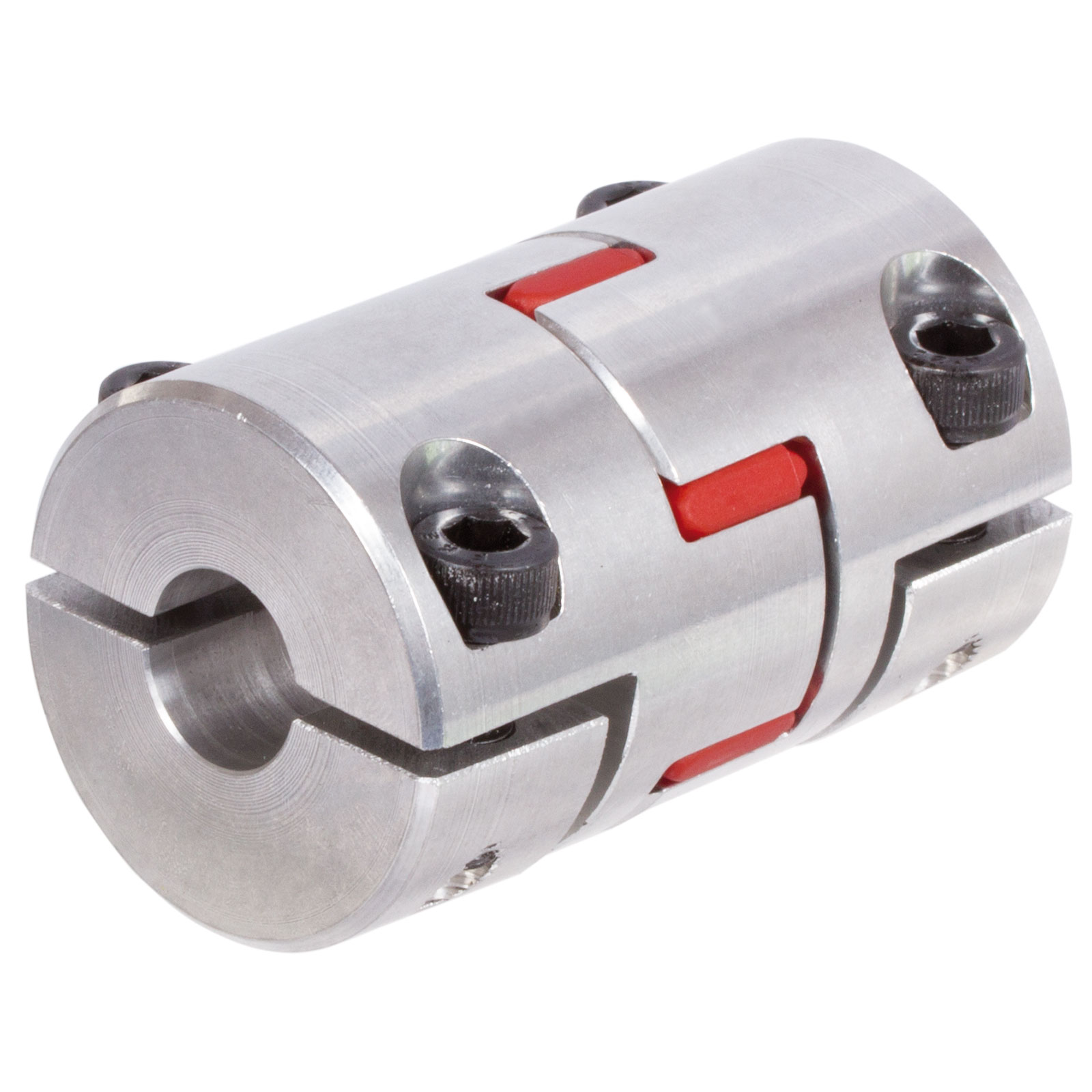
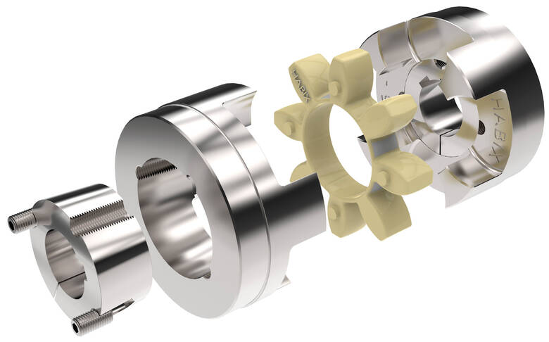
Another type of mechanical coupling is a jaw coupling. It is used in motion control and general low-power transmission applications. This type of coupling does not require lubrication and is capable of accommodating angular misalignment. Unlike other types of couplings, the jaw coupling uses two hubs with intermeshing jaws. The jaw coupling’s spider is typically made of copper alloys. In addition, it is suitable for shock and vibration loads.
Mechanical couplings can be made from a variety of materials. One popular choice is rubber. The material can be natural or chloroprene. These materials are flexible and can tolerate slight misalignment.
Electrical
Electrical coupling is the process in which a single electrical signal is transferred from a nerve cell to another. It occurs when electrical signals from two nerve cells interact with each other in a way similar to haptic transmission. This type of coupling can occur on its own or in combination with electrotonic coupling in gap junctions.
Electrical coupling is often associated with oscillatory behavior of neurons. The mechanism of electrical coupling is complex and is studied mathematically to understand its effect on oscillatory neuron networks. For example, electrical coupling can increase or decrease the frequency of an oscillator, depending on the state of the neuron coupled to it.
The site of coupling is usually the junction of opposing cell membranes. The cellular resistance and the coupling resistance are measured in voltage-clamp experiments. This type of coupling has a specific resistance of 100 O-cm. As a result, the coupling resistance varies with the frequency.
The authors of this study noted that electrotonic coupling depends on the ratio between the resistance of the nonjunctional membranes and the junctional membranes. The voltage attenuation technique helps reveal the differences in resistance and shunting through the intercellular medium. However, it is unclear whether electrotonic coupling is electrostatically mediated.
Electrical coupling has also been suggested to play a role in the intercellular transfer of information. There are many examples that support this theory. A message can be a distinct qualitative or quantitative signal, which results in a gradient in the cells. Although gap junctions are absent at many embryonic interaction sites, increasing evidence suggests a role in information transfer.
Flexible
When it comes to choosing the right Flexible Coupling, there are several factors that you should take into account. Among these factors is the backlash that can be caused by the movement of the coupling. The reason for this problem is the fact that couplings that do not have anti-fungal properties can be easily infected by mold. The best way to avoid this is to pay attention to the moisture content of the area where you are installing the coupling. By following these guidelines, you can ensure the best possible installation.
To ensure that you are getting the most out of your flexible couplings, you must consider their characteristics and how easy they are to install, assemble, and maintain. You should also look for elements that are field-replaceable. Another important factor is the coupling’s torsional rigidity. It should also be able to handle reactionary loads caused by misalignment.
Flexible couplings come in many different types. There are diaphragm and spiral couplings. These couplings allow for axial motion, angular misalignment, and parallel offset. They have one-piece construction and are made from stainless steel or aluminum. These couplings also offer high torsional stiffness, which is beneficial for applications requiring high torques.
Flexible couplings have several advantages over their rigid counterparts. They are designed to handle misalignments of up to seven degrees and 0.025 inches. These characteristics are important in motion control applications. Flexible couplings are also inexpensive, and they do not require maintenance.
Beam
A beam coupling is a type of mechanical coupling, usually one solid piece, that connects two mechanical parts. Its performance is largely determined by the material used. Typical materials include stainless steel, aluminum, Delrin, and titanium. The beam coupling is rated for different speeds and torques. The coupling should be selected according to the application. In addition to the material, the application should also consider the speed and torque of the system.
There are two main types of beam couplings. The first is the helical beam coupling, which has a continuous multi spiral cut. This type of coupling offers a high degree of flexibility and compensates for a high degree of misalignment. The second type of beam coupling is the helical shaft coupling, which has a low torsional stiffness, which makes it ideal for small torque applications.
Another type of beam coupling is the multiple beam design, which combines two beams. It allows for more tolerance in manufacturing and installation and protects expensive components from excessive bearing loads. It also helps keep beams shorter than a single beam coupling. This type of coupling also enables a higher torque capacity and torsional stiffness.
Beam couplings can be manufactured with different materials, including stainless steel and aluminum. The “A” series is available in aluminum and stainless steel and is ideal for general-purpose and light-duty applications. It is also economical and durable. This type of coupling can also be used with low torque pumps or encoder/resolver systems.
Pin & bush
The Pin & bush coupling is a versatile, general-purpose coupling with high tensile bolts and rubber bushes. It can tolerate a wide range of operating temperatures and is suitable for use in oil and water-resistance applications. Its unique design enables it to be used in either direction. In addition, it requires no lubrication.
The pin bush coupling is a fail-safe coupling with a long service life and is used for high-torque applications. It provides torsional flexibility and dampens shocks, making it a flexible coupling that protects equipment and reduces maintenance costs. Its hubs are forged from graded cast iron for strength and durability. Besides, the coupling’s elastomer elements reduce vibration and impact loads. It also accommodates a misalignment of up to 0.5 degrees.
Pin & bush couplings are a popular choice for a variety of different applications. This coupling features a protective flange design that protects the coupling flange from wear and tear. The coupling nut is secured to one flange, while a rubber or leather bush sits between the other flange. Its unique design makes it ideal for use in applications where misalignment is a small factor. The rubber bushing also helps absorb vibration and shock.
Mesh tooth
Mesh tooth couplings are used to transfer torque between two shafts and reduce backlash. However, mesh tooth couplings have some limitations. One disadvantage is the break-away friction factor in the axial direction. This problem is caused by the high contact force between the tooth and gear mesh. This can cause unpredictable forces on the shafts.
In this paper, we present a FEM model for mesh tooth coupling. We first validate the mesh density. To do so, we compute the bolt stress as a uniaxial tensile during the tightening process. We used different mesh sizes and mesh density to validate our results.
The mesh stiffness of gear pairs is influenced by lead crown relief and misalignment. For example, if one tooth is positioned too far in the axis, the mesh stiffness will be decreased. A misaligned gear pair will lose torque capacity. A mesh tooth coupling can be lubricated with oil.
An ideal mesh tooth coupling has no gaps between the teeth, which reduces the risk of uneven wear. The coupling’s quality exposed fasteners include SAE Grade 5 bolts. It also offers corrosion resistance. The couplings are compatible with industrial environments. They also eliminate the need for selective assembly in sleeve couplings.
editor by czh 2023-03-12
China Professional rongde unique high seal compact duty aluminium cnc stainless steel connect shaft helical flexible standard coupling flange coupling
Relevant Industries: Restaurant, Foodstuff Shop, Development works , Power & Mining, Marketing Firm
Composition: Jaw / Spider
Versatile or Rigid: Versatile
Standard or Nonstandard: Regular
Substance: Aluminium
Certification: CE & ISO9001
Outdoors diameter(D): 16-51mm
Duration: 22-51mm
standard bore: 3-25mm
rated torque: .4-14N
Max torque: .8-28N
Angular misalignment: 3
Max rotational velocity: 6000r/min
Packaging Particulars: Carton
Port: HangZhou
rongde exclusive substantial seal compact obligation aluminium cnc stainless metal connect shaft helical versatile common coupling
Adaptable couplings are utilized to transmit torque from 1 shaft to one more when the 2 shafts are a bit misaligned. It can accommodate different degrees of misalignment up to 3°. In addition to allowing for misalignment, it can also be utilised for vibration damping or sound reduction.Encoder couplings, adaptable coupling, couplings doing work with Encoder & all kinds of motors (servo motor, DC motor, AC motor, equipment motors).
Solution Pictures
Much more Items
Merchandise Testing
Packaing & Transport
Business Introduction
HangZhou CZPT Optics Co., Ltd. is located in the present day metropolis- Changhun which is know as the optoelectronics market base of China. Specializing in the creation of rotary encoders and other industrial automation sensor-connected goods, merchandise employed in pace measurement, angle measurement, duration measurement. To improve the company’s product sales and following-product sales community, we established up branch firm in ZheJiang , HangZhou, Xi’an, HangZhou and ZheJiang and many others.
*Exceptional top quality: professional R&D staff, stringent top quality screening.*Speedy response: an in depth income network to ensure timely and successful interaction.*Power to ensure: sufficient stock, the shortest guide time.*Tailored services: to meet up with the a variety of of needs from consumers.Right after-income service: merchandise warranty period of eighteen months.
The Exhibition And Photographs
Certificate
Our Service
1. The inquiries about the encoder will be answered within 24 hours.
two. A single-quit remedy will supply to meet all your needs on price range, developing and shipment.
three. We can offer you the information of supplier in your market if you want to make contact with them right.
4. Update the procession of producing.
five. Warranty eighteen months: Cost-free substitute of faulty goods inside of 18 months.
FAQ
Q1:Can I have a sample for screening?
A: Truly we have a quite very good price basic principle, when you make the bulk purchase then value of sample will be return to you. The price is the very same for fifty-one hundred sets which includes the sample
Q2:Can I insert my symbol on the encoder ?
A:Indeed,OEM and ODM are available for us. But you should ship us the Trademark authorization letter.
Q3:How can i get the right after-service?
A:We will send out you the spare parts by cost-free if the issues induced by us. If it is the men-produced difficulties,we also ship the spare areas,but you ought to pay out. For our variety hood motors it is lifelong servicing.
Q4 :Do you have inspection processes for encoder ?
A:100% self-inspection prior to packing
Q5:Can I have a pay a visit to to your manufacturing unit ahead of the order?
A: Certain,welcome to go to our manufacturing unit.
Listed here is our manufacturing facility handle: No.1666, Ya’an Street, Xihu (West Lake) Dis. District, Chanchun, China
We can select you up in the airport.
Make contact with US More detail info, welcome to pay a visit to our web site: .cn
An Overview of Worm Shafts and Gears
This article provides an overview of worm shafts and gears, including the type of toothing and deflection they experience. Other topics covered include the use of aluminum versus bronze worm shafts, calculating worm shaft deflection and lubrication. A thorough understanding of these issues will help you to design better gearboxes and other worm gear mechanisms. For further information, please visit the related websites. We also hope that you will find this article informative.
Double throat worm gears
The pitch diameter of a worm and the pitch of its worm wheel must be equal. The two types of worm gears have the same pitch diameter, but the difference lies in their axial and circular pitches. The pitch diameter is the distance between the worm’s teeth along its axis and the pitch diameter of the larger gear. Worms are made with left-handed or right-handed threads. The lead of the worm is the distance a point on the thread travels during one revolution of the worm gear. The backlash measurement should be made in a few different places on the gear wheel, as a large amount of backlash implies tooth spacing.
A double-throat worm gear is designed for high-load applications. It provides the tightest connection between worm and gear. It is crucial to mount a worm gear assembly correctly. The keyway design requires several points of contact, which block shaft rotation and help transfer torque to the gear. After determining the location of the keyway, a hole is drilled into the hub, which is then screwed into the gear.
The dual-threaded design of worm gears allows them to withstand heavy loads without slipping or tearing out of the worm. A double-throat worm gear provides the tightest connection between worm and gear, and is therefore ideal for hoisting applications. The self-locking nature of the worm gear is another advantage. If the worm gears are designed well, they are excellent for reducing speeds, as they are self-locking.
When choosing a worm, the number of threads that a worm has is critical. Thread starts determine the reduction ratio of a pair, so the higher the threads, the greater the ratio. The same is true for the worm helix angles, which can be one, two, or three threads long. This varies between a single thread and a double-throat worm gear, and it is crucial to consider the helix angle when selecting a worm.
Double-throat worm gears differ in their profile from the actual gear. Double-throat worm gears are especially useful in applications where noise is an issue. In addition to their low noise, worm gears can absorb shock loads. A double-throat worm gear is also a popular choice for many different types of applications. These gears are also commonly used for hoisting equipment. Its tooth profile is different from that of the actual gear.
Bronze or aluminum worm shafts
When selecting a worm, a few things should be kept in mind. The material of the shaft should be either bronze or aluminum. The worm itself is the primary component, but there are also addendum gears that are available. The total number of teeth on both the worm and the addendum gear should be greater than forty. The axial pitch of the worm needs to match the circular pitch of the larger gear.
The most common material used for worm gears is bronze because of its desirable mechanical properties. Bronze is a broad term referring to various copper alloys, including copper-nickel and copper-aluminum. Bronze is most commonly created by alloying copper with tin and aluminum. In some cases, this combination creates brass, which is a similar metal to bronze. The latter is less expensive and suitable for light loads.
There are many benefits to bronze worm gears. They are strong and durable, and they offer excellent wear-resistance. In contrast to steel worms, bronze worm gears are quieter than their counterparts. They also require no lubrication and are corrosion-resistant. Bronze worms are popular with small, light-weight machines, as they are easy to maintain. You can read more about worm gears in CZPT’s CZPT.
Although bronze or aluminum worm shafts are the most common, both materials are equally suitable for a variety of applications. A bronze shaft is often called bronze but may actually be brass. Historically, worm gears were made of SAE 65 gear bronze. However, newer materials have been introduced. SAE 65 gear bronze (UNS C90700) remains the preferred material. For high-volume applications, the material savings can be considerable.
Both types of worms are essentially the same in size and shape, but the lead on the left and right tooth surfaces can vary. This allows for precise adjustment of the backlash on a worm without changing the center distance between the worm gear. The different sizes of worms also make them easier to manufacture and maintain. But if you want an especially small worm for an industrial application, you should consider bronze or aluminum.
Calculation of worm shaft deflection
The centre-line distance of a worm gear and the number of worm teeth play a crucial role in the deflection of the rotor. These parameters should be entered into the tool in the same units as the main calculation. The selected variant is then transferred to the main calculation. The deflection of the worm gear can be calculated from the angle at which the worm teeth shrink. The following calculation is helpful for designing a worm gear.
Worm gears are widely used in industrial applications due to their high transmittable torques and large gear ratios. Their hard/soft material combination makes them ideally suited for a wide range of applications. The worm shaft is typically made of case-hardened steel, and the worm wheel is fabricated from a copper-tin-bronze alloy. In most cases, the wheel is the area of contact with the gear. Worm gears also have a low deflection, as high shaft deflection can affect the transmission accuracy and increase wear.
Another method for determining worm shaft deflection is to use the tooth-dependent bending stiffness of a worm gear’s toothing. By calculating the stiffness of the individual sections of a worm shaft, the stiffness of the entire worm can be determined. The approximate tooth area is shown in figure 5.
Another way to calculate worm shaft deflection is by using the FEM method. The simulation tool uses an analytical model of the worm gear shaft to determine the deflection of the worm. It is based on a two-dimensional model, which is more suitable for simulation. Then, you need to input the worm gear’s pitch angle and the toothing to calculate the maximum deflection.
Lubrication of worm shafts
In order to protect the gears, worm drives require lubricants that offer excellent anti-wear protection, high oxidation resistance, and low friction. While mineral oil lubricants are widely used, synthetic base oils have better performance characteristics and lower operating temperatures. The Arrhenius Rate Rule states that chemical reactions double every ten degrees C. Synthetic lubricants are the best choice for these applications.
Synthetics and compounded mineral oils are the most popular lubricants for worm gears. These oils are formulated with mineral basestock and four to six percent synthetic fatty acid. Surface-active additives give compounded gear oils outstanding lubricity and prevent sliding wear. These oils are suited for high-speed applications, including worm gears. However, synthetic oil has the disadvantage of being incompatible with polycarbonate and some paints.
Synthetic lubricants are expensive, but they can increase worm gear efficiency and operating life. Synthetic lubricants typically fall into two categories: PAO synthetic oils and EP synthetic oils. The latter has a higher viscosity index and can be used at a range of temperatures. Synthetic lubricants often contain anti-wear additives and EP (anti-wear).
Worm gears are frequently mounted over or under the gearbox. The proper lubrication is essential to ensure the correct mounting and operation. Oftentimes, inadequate lubrication can cause the unit to fail sooner than expected. Because of this, a technician may not make a connection between the lack of lube and the failure of the unit. It is important to follow the manufacturer’s recommendations and use high-quality lubricant for your gearbox.
Worm drives reduce backlash by minimizing the play between gear teeth. Backlash can cause damage if unbalanced forces are introduced. Worm drives are lightweight and durable because they have minimal moving parts. In addition, worm drives are low-noise and vibration. In addition, their sliding motion scrapes away excess lubricant. The constant sliding action generates a high amount of heat, which is why superior lubrication is critical.
Oils with a high film strength and excellent adhesion are ideal for lubrication of worm gears. Some of these oils contain sulfur, which can etch a bronze gear. In order to avoid this, it is imperative to use a lubricant that has high film strength and prevents asperities from welding. The ideal lubricant for worm gears is one that provides excellent film strength and does not contain sulfur.


editor by czh