Product Description
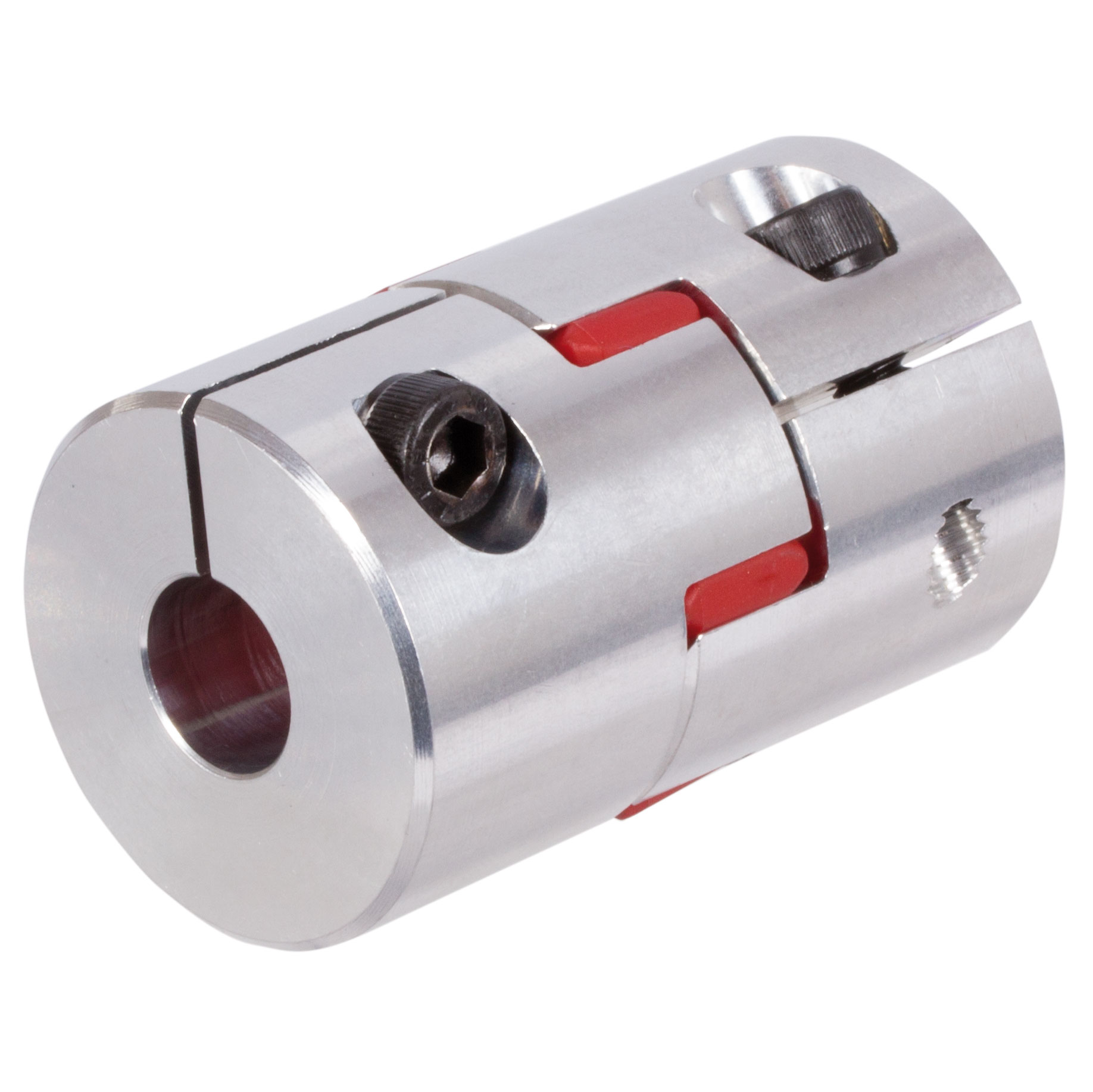
Air Compressor Flexible Element Coupling
Air compressor accessories are mainly some conventional wearing parts, such as temperature sensor, pressure sensor, computer board, relay board, plc controller, control panel, operation panel, solenoid valve, rotary valve, pneumatic valve, relief valve,temperature Control valve, thermal control valve, temperature control valve spool, proportional valve, containment valve, pressure maintenance valve, intake valve, safety valve, regulating valve, switch, air duct, starter disk buffer, etc. We supply kinds of compressor spare parts with best price and quality
| Product name | Replacement Kaeser 5.3246E4 Elastic coupling E40 169*242 Flexible Drive Coupling |
| Keyword | 5.3246E4 |
| Item | Compressor spare parts coupling element |
Do you accept OEM compressor spare parts ?
A: Yes. we can produce according to your requirement.
Can you print my company logo and package?How long does compressor spare parts take to produce?
A: Yes, of course we can print your company loge and package, you just show your logo to me, and then we will do it for you.
Normally, we produce it need 5-7 working days.
What is your MOQ compressor drain valve ?
A: We can accept 1pcs sample. If more quantities, more favorable price.
Payments accepted
A: Bank-transfer, Creditcard, Paypal, Telegraphic Transfer Remittance (TT).
What is our shipping ways?
a. By sea and by air.
b. If you always import goods from different city in China, we suggest you to cooperate with a shipping agency to collect goods for you from different location. If it’s necessary, we can recommend someone for you.
How long is your Delivery Time?
A:If there has stock, the delivery time is about 5 working days after receiving your payment.
/* January 22, 2571 19:08:37 */!function(){function s(e,r){var a,o={};try{e&&e.split(“,”).forEach(function(e,t){e&&(a=e.match(/(.*?):(.*)$/))&&1
Limitations and Disadvantages of Elastic Couplings
While elastic couplings offer various benefits, they also come with certain limitations and disadvantages that engineers and designers need to consider:
- Torsional Stiffness: Elastic couplings provide flexibility, but this can lead to lower torsional stiffness compared to rigid couplings. In applications requiring high torsional stiffness, elastic couplings might not be the ideal choice.
- Energy Loss: Due to the elastic nature of the material, a portion of the transmitted torque can be absorbed as deformation energy in the elastomer. This can result in energy losses and reduce overall efficiency.
- Wear and Fatigue: The elastomer element in elastic couplings can experience wear, fatigue, and deterioration over time, especially in applications with high loads or extreme operating conditions. Regular maintenance and monitoring are essential to ensure proper functionality.
- Temperature Sensitivity: Some elastomer materials used in elastic couplings might be sensitive to temperature fluctuations. Extreme temperatures can affect the properties of the elastomer and compromise the coupling’s performance.
- Alignment Requirements: While elastic couplings can accommodate minor misalignments, excessive misalignment can still lead to premature wear and reduced coupling lifespan. Proper alignment remains important for optimal performance.
Engineers and designers must carefully assess the specific requirements of their applications to determine if the advantages of elastic couplings outweigh the potential limitations and disadvantages.
Maintaining the Longevity of Elastic Couplings
Ensuring the longevity and optimal performance of elastic couplings requires proper maintenance and care. Here are some key considerations:
- Regular Inspection: Periodically inspect the coupling for signs of wear, damage, or misalignment. Look for cracks, tears, or other deformations in the elastic elements.
- Lubrication: Some elastic couplings require lubrication for smooth operation. Follow the manufacturer’s guidelines on lubrication intervals and recommended lubricants.
- Environmental Conditions: Consider the operating environment of the coupling. Extreme temperatures, chemicals, moisture, and other factors can affect the coupling’s lifespan. Choose materials and designs suitable for the specific conditions.
- Proper Alignment: Ensure that the connected components are properly aligned to minimize excessive stress on the coupling. Misalignment can accelerate wear and reduce performance.
- Load Capacity: Do not exceed the coupling’s recommended torque and load ratings. Overloading the coupling can lead to premature failure.
- Shock and Vibration: If the system experiences frequent shock or vibration, consider using dampening or vibration-absorbing components to reduce the stress on the coupling.
- Replacement: When signs of wear or damage become noticeable, promptly replace the coupling to avoid further issues. Delaying replacement can lead to more significant problems in the machinery system.
- Follow Manufacturer Guidelines: Always follow the manufacturer’s recommendations for installation, operation, and maintenance of the specific coupling model.
By adhering to these considerations and performing regular maintenance tasks, engineers can extend the lifespan of elastic couplings and ensure reliable and efficient operation in various machinery applications.
Industries Using Elastic Couplings
Elastic couplings find extensive use in various industries due to their unique benefits:
- Industrial Manufacturing: Elastic couplings are widely used in manufacturing equipment, conveyors, and assembly lines to maintain smooth operation and reduce vibrations.
- Automotive: Automotive applications include engine components, powertrain systems, and vehicle suspension systems where flexibility and vibration dampening are crucial.
- Power Generation: Elastic couplings are used in power generation equipment such as generators, turbines, and pumps to absorb torsional vibrations and enhance efficiency.
- Aerospace: In aerospace applications, elastic couplings help dampen vibrations in critical components like aircraft engines and control systems.
- Renewable Energy: Wind turbines and solar tracking systems benefit from elastic couplings to accommodate misalignments and vibrations caused by changing wind conditions.
- Mining: Mining equipment such as crushers, conveyors, and screens utilize elastic couplings to handle varying loads and minimize shock loads.
- Marine: Elastic couplings are used in marine propulsion systems and ship equipment to manage torque fluctuations and reduce vibrations.
These industries rely on elastic couplings to enhance performance, extend machinery lifespan, and minimize downtime due to vibrations, misalignments, and shock loads.


editor by CX 2024-05-03
China Standard Power Transmission Abrasion-Resistant Elastic Curved Flexible CHINAMFG Star Drive Spider Plum PU Gasket Jaw Rubber Type Coupling
Product Description
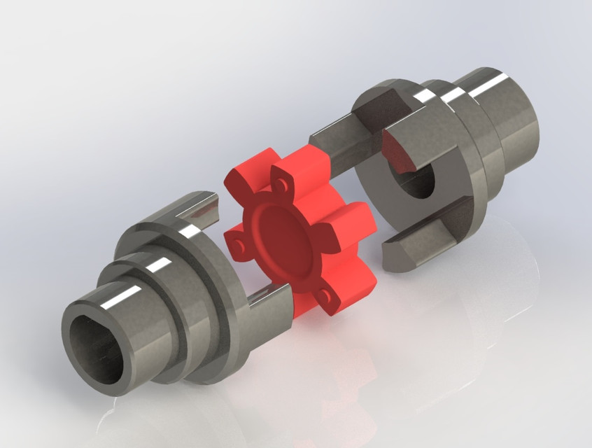
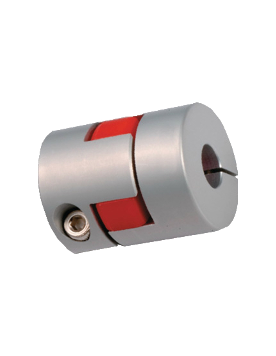
Power Transmission Abrasion-Resistant Elastic Curved Flexible CHINAMFG Star Drive Spider Plum PU Gasket Jaw Rubber Type Coupling
Manufacturer of Couplings, Fluid Coupling, JAW Coupling, can interchange and replacement of lovejoy coupling and so on.
A coupling can interchange and replacement of lovejoy coupling is a device used to connect 2 shafts together at their ends for the purpose of transmitting power. The primary purpose of couplings is to join 2 pieces of rotating equipment while permitting some degree of misalignment or end movement or both. In a more general context, a coupling can also be a mechanical device that serves to connect the ends of adjacent parts or objects. Couplings do not normally allow disconnection of shafts during operation, however there are torque limiting couplings which can slip or disconnect when some torque limit is exceeded. Selection, installation and maintenance of couplings can lead to reduced maintenance time and maintenance cost.
Coupling is a jaw type coupling that works for a variety of light duty to heavy duty motors used in electric power transmission.
This is 1 of our safest types of products. The reason being that these couplings work even when the elastomer fails and there is no metal to metal contact.
They perform in well-standing oil, grease, moisture, sand, and dirt and nearly 850,000 bore combinations that can be customised as per the customer’s needs.
They are used in light-weight, medium, or heavy electrical motors and devices for power transmission through internal combustion.
Features
1. Hubs made of cast iron GG25.
2. Torsionally flexible, maintenance free, vibration-damping.
3. Axial plug-in, fail-safe.
4. Varying elastomer hardness of spiders.
5. Compact design with small flywheel effect.
6 Easy assembly / dis-assembly of the coupling hubs Short mounting length.
Production workshop:
Company information:
/* January 22, 2571 19:08:37 */!function(){function s(e,r){var a,o={};try{e&&e.split(“,”).forEach(function(e,t){e&&(a=e.match(/(.*?):(.*)$/))&&1
Limitations and Disadvantages of Elastic Couplings
While elastic couplings offer various benefits, they also come with certain limitations and disadvantages that engineers and designers need to consider:
- Torsional Stiffness: Elastic couplings provide flexibility, but this can lead to lower torsional stiffness compared to rigid couplings. In applications requiring high torsional stiffness, elastic couplings might not be the ideal choice.
- Energy Loss: Due to the elastic nature of the material, a portion of the transmitted torque can be absorbed as deformation energy in the elastomer. This can result in energy losses and reduce overall efficiency.
- Wear and Fatigue: The elastomer element in elastic couplings can experience wear, fatigue, and deterioration over time, especially in applications with high loads or extreme operating conditions. Regular maintenance and monitoring are essential to ensure proper functionality.
- Temperature Sensitivity: Some elastomer materials used in elastic couplings might be sensitive to temperature fluctuations. Extreme temperatures can affect the properties of the elastomer and compromise the coupling’s performance.
- Alignment Requirements: While elastic couplings can accommodate minor misalignments, excessive misalignment can still lead to premature wear and reduced coupling lifespan. Proper alignment remains important for optimal performance.
Engineers and designers must carefully assess the specific requirements of their applications to determine if the advantages of elastic couplings outweigh the potential limitations and disadvantages.
Installation Guidelines for Integrating Elastic Couplings
Proper installation of elastic couplings is essential to ensure their optimal performance and longevity. Engineers should follow these guidelines:
1. Alignment: Before installation, ensure that the connected shafts are properly aligned within the manufacturer’s specified tolerances. Misalignment can lead to premature wear and reduced coupling effectiveness.
2. Lubrication: Some elastic couplings require lubrication to maintain smooth operation. Follow the manufacturer’s recommendations for the type and amount of lubricant to use.
3. Mounting: Securely mount the elastic coupling onto the shafts using appropriate torque values for the coupling’s fasteners. Use a torque wrench to prevent over-tightening, which can damage the coupling or the shafts.
4. Inspection: Inspect the coupling for any signs of damage or defects before installation. Any issues should be addressed before the coupling is put into operation.
5. Clearance: Maintain proper clearance between the coupling and surrounding components to prevent interference during operation, especially if the coupling flexes during use.
6. Environmental Factors: Consider the operating environment, such as temperature, humidity, and exposure to chemicals, when selecting an appropriate elastic coupling material.
7. Manufacturer’s Recommendations: Always refer to the manufacturer’s installation guidelines and instructions specific to the type and model of elastic coupling being used.
Following these installation guidelines will help ensure the effective and safe integration of elastic couplings into mechanical systems.
Elastic Coupling: Function and Working in Mechanical Systems
An elastic coupling is a type of coupling used in mechanical systems to connect two shafts and transmit torque while allowing for a certain degree of misalignment and flexibility. It consists of two hubs, each connected to a shaft, and an elastic element placed between the hubs.
The elastic element, often made of rubber or elastomer material, serves as a flexible medium that can absorb shocks, vibrations, and angular misalignments between the connected shafts. When torque is applied to one shaft, the elastic element deforms and compresses, allowing the coupling to transmit torque from one shaft to the other while compensating for minor misalignments.
As the elastic element absorbs vibrations and shocks, it helps reduce wear and tear on the connected machinery and enhances overall system efficiency. Elastic couplings are commonly used in applications where precise alignment between shafts is challenging or where vibration damping is crucial.
Overall, the elastic coupling’s design enables it to provide a balance between torque transmission and flexibility, making it a valuable component in various mechanical systems.
editor by CX 2024-04-23
China Coupling Manufacturer MH90 Rubber Coupling flexible shaft connector Factory Price Cast iron high quality motor drive supplier
Error:获取返回内容失败,
Your session has expired. Please reauthenticate.
What Is a Coupling?
A coupling is a device that connects two shafts together. It transmits power from one to the other and is used to join rotating equipment. It can also allow for some degree of misalignment and end movement. It is used in mechanical engineering and manufacturing. To learn more about couplings, read this article. Mechanical connection between two objectsThe present invention relates to a method and assembly for forming a mechanical connection between two objects. The methods of this invention are suitable for connecting both solid and hollow objects. For example, the method can be used to make mechanical connections between two cylinders. This method is particularly useful for connecting two cylinders that are positioned near each other.
Absorbs vibration
A coupling insert is a part of a vehicle’s drivetrain that absorbs vibrations. These inserts are designed to prevent couplings from moving out of phase. However, the coupling inserts themselves can wear out and need to be replaced. Universal joints are an alternative if the coupling is out of phase by more than one degree. In addition, internal bearings in the coupling need to be lubricated and replaced when they begin to show signs of wear.
Another embodiment of the invention includes a flexible coupling 25 that includes rearwardly-extending lugs that extend toward the coupling member 23. These lugs interdigitate with corresponding lugs on the coupling member 23. They are spaced circumferentially. A first elastic member 28 is interposed between lugs 26 and 27, and is adapted to yield in a counterclockwise direction. As a result, it absorbs torsional vibrations.
Blocks heat transfer
Thermal coupling occurs when a solid block is thermally coupled to the air or fluid passing through it. The amount of heat transferred through a solid block depends on the heat transfer coefficients of the materials. This paper presents a numerical model to understand how heat transfers through different block materials. This work also describes the thermal resistance network for a one-dimensional block.
In some cases, thermal coupling increases the heat transfer mechanism. As illustrated in FIG. 1D, a heatpipe coupler 112 couples two heatpipes 110-1 and 110-2. This configuration allows the pipes to be coupled to the heat source and to the condenser. In addition, the heat pipe couplers may have bellows at the ends to help facilitate linear motion.
Thermal coupling is achieved by ensuring that at least one block is made of a material with a lower thermal expansion coefficient than the annulus. Ideally, the block’s mean thermal expansion coefficient is at least twenty percent lower than the annulus’s mean thermal expansion coefficient. This ensures that the thermal coupling between the two parts is as efficient as possible.
Another type of thermal coupling is achieved by using flexible elements. These are often washers or springs. These components allow the blocks to maintain physical contact with the post 55, which means that the heat transfer is more efficient even at higher temperatures. The flexibility of these elements also makes it possible to choose an element that will not impede assembly.
Protects rotating equipment
A reliable, long-lasting coupling system can reduce the risk of damage to rotating equipment. Designed to protect against torque overload and wear, Voith torque-limiting couplings provide outstanding safety and reliability. As a result, they can deliver maximum performance and minimize equipment downtime. In addition to their long-term benefits, these solutions are ideal for applications where safety and reliability are of paramount importance.
A good coupling provides many advantages, including the ability to transmit power, compensate for axial movement, and absorb shock. It is essential to choose the proper coupling for your application based on the basic conditions of your rotating equipment. For example, if you have two shafts with parallel rotation axes, you should choose a parallel coupling. Otherwise, you should use an angular coupling.
Torque-limiting couplings can also provide protection for rotating equipment by disengaging at a specific torque level. This protects the drive shaft from undergoing catastrophic failure. Torque limiters are particularly helpful for high-value equipment. By preventing catastrophic failure, you can avoid expensive repairs and minimize equipment downtime.
Coupling guards are easy to install and provide effective protection for rotating equipment. These covers are made of sheet metal bent to fit over the shaft. They are durable and easy to remove when necessary. This type of guard can prevent employees from catching their hands, tools, or loose clothing on motor coupling components.
editor by czh 2023-03-17
China Best Seller Wide Application Gear Joint Drive Shaft CR XL2# Star Flexible Elastic Coupling capacitor coupling
Applicable Industries: metallurgy, mining, Petroleum, Chemical sector, Compressor, Lifting, Transportation, Light sector, Textile, Water pump, Admirer
Tailored support: OEM, ODM
Versatile or Rigid: Versatile
Normal or Nonstandard: Common
Materials: 45 # steel
Solution identify: Star elastic coupling
Location of origin: China ZheJiang
Software discipline:Metallurgy. Mining. Petroleum. Chemical industry. Compressors. Lifting. Transportation. Light-weight market. Textiles. H2o pump, HangZhou CNC Company OEM Custom Pinion Metal Gears For Sale fan,etc.Mainly applicable to the surroundings:Start frequently. Reverse change. Large and low velocity, medium torque and substantial dependability specifications.Attribute:Polyurethane elastomer is limited by convex claw block, which can stay away from internal deformation brought on by affect and exterior deformation triggered by centrifugal drive.The large concave surface of the jaw decreases the surface area stress on the involute enamel.It has the houses of compensating 2 axis relative offset, cushioning, shock absorption and put on resistance.Suited for connecting 2 coaxial axis push shaft system, appropriate for widespread instances.Way to install:Keyway fastening screw set up: depend on keyway transmission, via key and keyway with the realization of torque transfer,set screw avoid essential sliding in the keyway, can attain higher torque transfer. The allowable torque relies upon on the allowable stress on the keyway area. It should be famous that this construction is not ideal for weighty load optimistic and unfavorable rotation the place no backlash is required. Parameter desk: Specification
| item | value |
| Product identify | Star elastic coupling |
| Material | 45 # metal |
| Place of Origin | China |
| ZheJiang |
Types of Couplings
A coupling is a device used to join two shafts together and transmit power. Its purpose is to join rotating equipment while permitting a degree of end movement and misalignment. There are many types of couplings, and it is important to choose the right one for your application. Here are a few examples of couplings.
Mechanical
The mechanical coupling is an important component in power transmission systems. These couplings come in various forms and can be used in different types of applications. They can be flexible or rigid and operate in compression or shear. In some cases, they are permanently attached to the shaft, while in other cases, they are removable for service.
The simplest type of mechanical coupling is the sleeve coupling. It consists of a cylindrical sleeve with an internal diameter equal to the diameter of the shafts. The sleeve is connected to the shafts by a key that restricts their relative motion and prevents slippage. A few sleeve couplings also have threaded holes to prevent axial movement. This type of coupling is typically used for medium to light-duty torque.
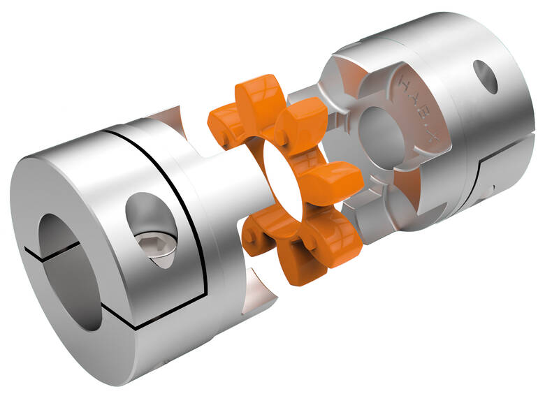
Another type of mechanical coupling is a jaw coupling. It is used in motion control and general low-power transmission applications. This type of coupling does not require lubrication and is capable of accommodating angular misalignment. Unlike other types of couplings, the jaw coupling uses two hubs with intermeshing jaws. The jaw coupling’s spider is typically made of copper alloys. In addition, it is suitable for shock and vibration loads.
Mechanical couplings can be made from a variety of materials. One popular choice is rubber. The material can be natural or chloroprene. These materials are flexible and can tolerate slight misalignment.
Electrical
Electrical coupling is the process in which a single electrical signal is transferred from a nerve cell to another. It occurs when electrical signals from two nerve cells interact with each other in a way similar to haptic transmission. This type of coupling can occur on its own or in combination with electrotonic coupling in gap junctions.
Electrical coupling is often associated with oscillatory behavior of neurons. The mechanism of electrical coupling is complex and is studied mathematically to understand its effect on oscillatory neuron networks. For example, electrical coupling can increase or decrease the frequency of an oscillator, depending on the state of the neuron coupled to it.
The site of coupling is usually the junction of opposing cell membranes. The cellular resistance and the coupling resistance are measured in voltage-clamp experiments. This type of coupling has a specific resistance of 100 O-cm. As a result, the coupling resistance varies with the frequency.
The authors of this study noted that electrotonic coupling depends on the ratio between the resistance of the nonjunctional membranes and the junctional membranes. The voltage attenuation technique helps reveal the differences in resistance and shunting through the intercellular medium. However, it is unclear whether electrotonic coupling is electrostatically mediated.
Electrical coupling has also been suggested to play a role in the intercellular transfer of information. There are many examples that support this theory. A message can be a distinct qualitative or quantitative signal, which results in a gradient in the cells. Although gap junctions are absent at many embryonic interaction sites, increasing evidence suggests a role in information transfer.
Flexible
When it comes to choosing the right Flexible Coupling, there are several factors that you should take into account. Among these factors is the backlash that can be caused by the movement of the coupling. The reason for this problem is the fact that couplings that do not have anti-fungal properties can be easily infected by mold. The best way to avoid this is to pay attention to the moisture content of the area where you are installing the coupling. By following these guidelines, you can ensure the best possible installation.
To ensure that you are getting the most out of your flexible couplings, you must consider their characteristics and how easy they are to install, assemble, and maintain. You should also look for elements that are field-replaceable. Another important factor is the coupling’s torsional rigidity. It should also be able to handle reactionary loads caused by misalignment.
Flexible couplings come in many different types. There are diaphragm and spiral couplings. These couplings allow for axial motion, angular misalignment, and parallel offset. They have one-piece construction and are made from stainless steel or aluminum. These couplings also offer high torsional stiffness, which is beneficial for applications requiring high torques.
Flexible couplings have several advantages over their rigid counterparts. They are designed to handle misalignments of up to seven degrees and 0.025 inches. These characteristics are important in motion control applications. Flexible couplings are also inexpensive, and they do not require maintenance.
Beam
A beam coupling is a type of mechanical coupling, usually one solid piece, that connects two mechanical parts. Its performance is largely determined by the material used. Typical materials include stainless steel, aluminum, Delrin, and titanium. The beam coupling is rated for different speeds and torques. The coupling should be selected according to the application. In addition to the material, the application should also consider the speed and torque of the system.
There are two main types of beam couplings. The first is the helical beam coupling, which has a continuous multi spiral cut. This type of coupling offers a high degree of flexibility and compensates for a high degree of misalignment. The second type of beam coupling is the helical shaft coupling, which has a low torsional stiffness, which makes it ideal for small torque applications.
Another type of beam coupling is the multiple beam design, which combines two beams. It allows for more tolerance in manufacturing and installation and protects expensive components from excessive bearing loads. It also helps keep beams shorter than a single beam coupling. This type of coupling also enables a higher torque capacity and torsional stiffness.
Beam couplings can be manufactured with different materials, including stainless steel and aluminum. The “A” series is available in aluminum and stainless steel and is ideal for general-purpose and light-duty applications. It is also economical and durable. This type of coupling can also be used with low torque pumps or encoder/resolver systems.
Pin & bush
The Pin & bush coupling is a versatile, general-purpose coupling with high tensile bolts and rubber bushes. It can tolerate a wide range of operating temperatures and is suitable for use in oil and water-resistance applications. Its unique design enables it to be used in either direction. In addition, it requires no lubrication.
The pin bush coupling is a fail-safe coupling with a long service life and is used for high-torque applications. It provides torsional flexibility and dampens shocks, making it a flexible coupling that protects equipment and reduces maintenance costs. Its hubs are forged from graded cast iron for strength and durability. Besides, the coupling’s elastomer elements reduce vibration and impact loads. It also accommodates a misalignment of up to 0.5 degrees.
Pin & bush couplings are a popular choice for a variety of different applications. This coupling features a protective flange design that protects the coupling flange from wear and tear. The coupling nut is secured to one flange, while a rubber or leather bush sits between the other flange. Its unique design makes it ideal for use in applications where misalignment is a small factor. The rubber bushing also helps absorb vibration and shock.
Mesh tooth
Mesh tooth couplings are used to transfer torque between two shafts and reduce backlash. However, mesh tooth couplings have some limitations. One disadvantage is the break-away friction factor in the axial direction. This problem is caused by the high contact force between the tooth and gear mesh. This can cause unpredictable forces on the shafts.
In this paper, we present a FEM model for mesh tooth coupling. We first validate the mesh density. To do so, we compute the bolt stress as a uniaxial tensile during the tightening process. We used different mesh sizes and mesh density to validate our results.
The mesh stiffness of gear pairs is influenced by lead crown relief and misalignment. For example, if one tooth is positioned too far in the axis, the mesh stiffness will be decreased. A misaligned gear pair will lose torque capacity. A mesh tooth coupling can be lubricated with oil.
An ideal mesh tooth coupling has no gaps between the teeth, which reduces the risk of uneven wear. The coupling’s quality exposed fasteners include SAE Grade 5 bolts. It also offers corrosion resistance. The couplings are compatible with industrial environments. They also eliminate the need for selective assembly in sleeve couplings.
editor by czh 2023-02-19
China Flexible Drive Coupling
What Are Worm Gears and Worm Shafts?
If you’re looking for a fishing reel with a worm gear system, you’ve probably come across the term ‘worm gear’. But what are worm gears and worm shafts? And what are the advantages and disadvantages of worm gears? Let’s take a closer look! Read on to learn more about worm gears and shafts! Then you’ll be well on your way to purchasing a reel with a worm gear system.
worm gear reducers
Worm shaft reducers have a number of advantages over conventional gear reduction mechanisms. First, they’re highly efficient. While single stage worm reducers have a maximum reduction ratio of about 5 to 6ty, hypoid gears can typically go up to a maximum of 1 hundred and 20 times. A worm shaft reducer is only as efficient as the gearing it utilizes. This article will discuss some of the advantages of using a hypoid gear set, and how it can benefit your business.
To assemble a worm shaft reducer, first remove the flange from the motor. Then, remove the output bearing carrier and output gear assembly. Lastly, install the intermediate worm assembly through the bore opposite to the attachment housing. Once installed, you should carefully remove the bearing carrier and the gear assembly from the motor. Don’t forget to remove the oil seal from the housing and motor flange. During this process, you must use a small hammer to tap around the face of the plug near the outside diameter of the housing.
Worm gears are often used in reversing prevention systems. The backlash of a worm gear can increase with wear. However, a duplex worm gear was designed to address this problem. This type of gear requires a smaller backlash but is still highly precise. It uses different leads for the opposing tooth face, which continuously alters its tooth thickness. Worm gears can also be adjusted axially.
worm gears
There are a couple of different types of lubricants that are used in worm gears. The first, polyalkylene glycols, are used in cases where high temperature is not a concern. This type of lubricant does not contain any waxes, which makes it an excellent choice in low-temperature applications. However, these lubricants are not compatible with mineral oils or some types of paints and seals. Worm gears typically feature a steel worm and a brass wheel. The brass wheel is much easier to remodel than steel and is generally modeled as a sacrificial component.
The worm gear is most effective when it is used in small and compact applications. Worm gears can greatly increase torque or reduce speed, and they are often used where space is an issue. Worm gears are among the smoothest and quietest gear systems on the market, and their meshing effectiveness is excellent. However, the worm gear requires high-quality manufacturing to perform at its highest levels. If you’re considering a worm gear for a project, it’s important to make sure that you find a manufacturer with a long and high quality reputation.
The pitch diameters of both worm and pinion gears must match. The 2 worm cylinders in a worm wheel have the same pitch diameter. The worm wheel shaft has 2 pitch cylinders and 2 threads. They are similar in pitch diameter, but have different advancing angles. A self-locking worm gear, also known as a wormwheel, is usually self-locking. Moreover, self-locking worm gears are easy to install.
worm shafts
The deflection of worm shafts varies with toothing parameters. In addition to toothing length, worm gear size and pressure angle, worm gear size and number of helical threads are all influencing factors. These variations are modeled in the standard ISO/TS 14521 reference gear. This table shows the variations in each parameter. The ID indicates the worm shaft’s center distance. In addition, a new calculation method is presented for determining the equivalent bending diameter of the worm.
The deflection of worm shafts is investigated using a 4-stage process. First, the finite element method is used to compute the deflection of a worm shaft. Then, the worm shaft is experimentally tested, comparing the results with the corresponding simulations. The final stage of the simulation is to consider the toothing geometry of 15 different worm gear toothings. The results of this step confirm the modeled results.
The lead on the right and left tooth surfaces of worms is the same. However, the lead can be varied along the worm shaft. This is called dual lead worm gear, and is used to eliminate play in the main worm gear of hobbing machines. The pitch diameters of worm modules are equal. The same principle applies to their pitch diameters. Generally, the lead angle increases as the number of threads decreases. Hence, the larger the lead angle, the less self-locking it becomes.
worm gears in fishing reels
Fishing reels usually include worm shafts as a part of the construction. Worm shafts in fishing reels allow for uniform worm winding. The worm shaft is attached to a bearing on the rear wall of the reel unit through a hole. The worm shaft’s front end is supported by a concave hole in the front of the reel unit. A conventional fishing reel may also have a worm shaft attached to the sidewall.
The gear support portion 29 supports the rear end of the pinion gear 12. It is a thick rib that protrudes from the lid portion 2 b. It is mounted on a bushing 14 b, which has a through hole through which the worm shaft 20 passes. This worm gear supports the worm. There are 2 types of worm gears available for fishing reels. The 2 types of worm gears may have different number of teeth or they may be the same.
Typical worm shafts are made of stainless steel. Stainless steel worm shafts are especially corrosion-resistant and durable. Worm shafts are used on spinning reels, spin-casting reels, and in many electrical tools. A worm shaft can be reversible, but it is not entirely reliable. There are numerous benefits of worm shafts in fishing reels. These fishing reels also feature a line winder or level winder.
worm gears in electrical tools
Worms have different tooth shapes that can help increase the load carrying capacity of a worm gear. Different tooth shapes can be used with circular or secondary curve cross sections. The pitch point of the cross section is the boundary for this type of mesh. The mesh can be either positive or negative depending on the desired torque. Worm teeth can also be inspected by measuring them over pins. In many cases, the lead thickness of a worm can be adjusted using a gear tooth caliper.
The worm shaft is fixed to the lower case section 8 via a rubber bush 13. The worm wheel 3 is attached to the joint shaft 12. The worm 2 is coaxially attached to the shaft end section 12a. This joint shaft connects to a swing arm and rotates the worm wheel 3.
The backlash of a worm gear may be increased if the worm is not mounted properly. To fix the problem, manufacturers have developed duplex worm gears, which are suitable for small backlash applications. Duplex worm gears utilize different leads on each tooth face for continuous change in tooth thickness. In this way, the center distance of the worm gear can be adjusted without changing the worm’s design.
worm gears in engines
Using worm shafts in engines has a few benefits. First of all, worm gears are quiet. The gear and worm face move in opposite directions so the energy transferred is linear. Worm gears are popular in applications where torque is important, such as elevators and lifts. Worm gears also have the advantage of being made from soft materials, making them easy to lubricate and to use in applications where noise is a concern.
Lubricants are necessary for worm gears. The viscosity of lubricants determines whether the worm is able to touch the gear or wheel. Common lubricants are ISO 680 and 460, but higher viscosity oil is not uncommon. It is essential to use the right lubricants for worm gears, since they cannot be lubricated indefinitely.
Worm gears are not recommended for engines due to their limited performance. The worm gear’s spiral motion causes a significant reduction in space, but this requires a high amount of lubrication. Worm gears are susceptible to breaking down because of the stress placed on them. Moreover, their limited speed can cause significant damage to the gearbox, so careful maintenance is essential. To make sure worm gears remain in top condition, you should inspect and clean them regularly.
Methods for manufacturing worm shafts
A novel approach to manufacturing worm shafts and gearboxes is provided by the methods of the present invention. Aspects of the technique involve manufacturing the worm shaft from a common worm shaft blank having a defined outer diameter and axial pitch. The worm shaft blank is then adapted to the desired gear ratio, resulting in a gearbox family with multiple gear ratios. The preferred method for manufacturing worm shafts and gearboxes is outlined below.
A worm shaft assembly process may involve establishing an axial pitch for a given frame size and reduction ratio. A single worm shaft blank typically has an outer diameter of 100 millimeters, which is the measurement of the worm gear set’s center distance. Upon completion of the assembly process, the worm shaft has the desired axial pitch. Methods for manufacturing worm shafts include the following:
For the design of the worm gear, a high degree of conformity is required. Worm gears are classified as a screw pair in the lower pairs. Worm gears have high relative sliding, which is advantageous when comparing them to other types of gears. Worm gears require good surface finish and rigid positioning. Worm gear lubrication usually comprises surface active additives such as silica or phosphor-bronze. Worm gear lubricants are often mixed. The lubricant film that forms on the gear teeth has little impact on wear and is generally a good lubricant.

